When a pressure, temperature, or displacement signal is stable at rest but drifts as soon as a motor, cylinder, or moving table starts, the sensor is not the only possible cause. The connector interface, cable strain, shielding, grounding, power supply, and acquisition settings all belong in the same diagnostic chain. If gently supporting the cable, pressing the connector body, or reseating the interface changes the reading, inspect the connection before replacing the sensor.
This guide explains how contact stability, insulation, locking, and cable restraint work together in a circular connector, then turns those principles into a practical fault-isolation workflow.
Quick answer: what should you check first?
- Compare the signal with the machine stationary and moving under the same acquisition settings.
- Secure the cable so its weight and motion do not load the connector, then repeat the test.
- Confirm complete mating, correct key alignment, clean contacts, and an undamaged shell and insulator.
- Check the cable termination and rear clamp for movement; do not rely on a continuity beep alone.
- Compare the signal waveform with motor switching, servo motion, and other possible interference sources.
- Verify grounding, shielding, supply stability, and input configuration before assigning the fault to one component.
Why vibration can appear as an electrical problem
An analog measurement travels through more than the sensing element. It passes through the sensor leads, cable conductors, terminations, connector contacts, shielding and ground paths, and the acquisition input. A connector can remain physically mated while its electrical condition changes under cable pull or vibration.
Possible mechanisms include a damaged termination, insufficient contact force, contamination, fretting at the contact interface, or a cable whose motion is transferred directly into the rear of the connector. These conditions may produce a slow offset, intermittent step changes, or differences between repeated measurements. Electromagnetic coupling can produce similar symptoms, so the waveform and operating sequence matter.
Avoid diagnosing solely by appearance. A connector may look fully seated yet have a loose rear termination, and a cable may pass a static continuity test while failing when flexed. Conversely, a signal that changes during machine motion may come from grounding or interference rather than the connector.
The four structural layers that influence stability
1. The contact interface
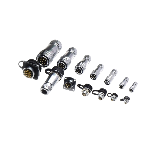
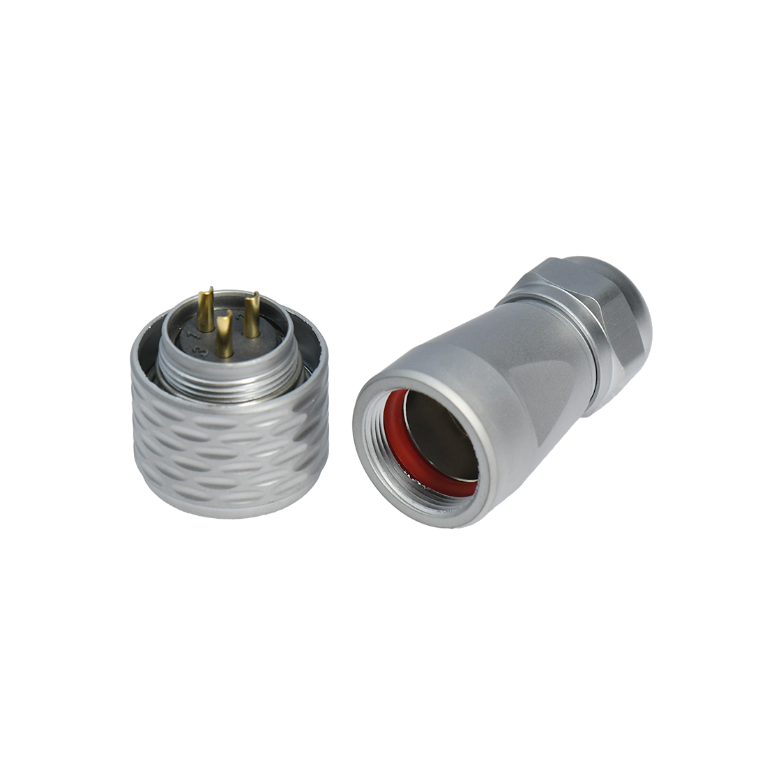
This DF product family uses gold-plated copper-alloy contacts. Gold plating can help maintain a stable conductive interface when the plating system, base material, contact geometry, and mating force are appropriate for the application. It does not make an interface immune to contamination, wear, incorrect mating, or mechanical overload.
Inspect for discoloration, bent contacts, recessed contacts, foreign material, or evidence that a pin is not entering its intended socket. Never scrape plated contacts with an abrasive. Follow the approved cleaning method for the connector and allow any cleaning agent to dry before energizing the circuit.
2. Insulator support and alignment
The insulator holds the contacts in position and maintains separation between circuits and the shell. The DF product specification identifies a PPS insulator and lists 2,000 MΩ insulation resistance for the family. Confirm that value against the exact part number and test conditions.
Cracks, heat damage, chemical attack, or a displaced insert can change alignment even when the metal shell appears intact. If an insulation-resistance problem is suspected, isolate both ends and use the method and test voltage permitted by the connected equipment.
3. Locking and mating retention
A locking system must keep the mating halves in the intended position while the equipment vibrates or the cable moves. The DF design uses a quick-locking arrangement with retaining and pressure-spring elements. Correct operation still depends on alignment, complete engagement, compatible mating halves, and an undamaged locking path.
Check that the connector reaches its defined locked position without forcing it. A lock that feels unusually light, rough, or inconsistent deserves inspection. Do not use external tape as a substitute for a damaged retention mechanism.
4. Cable restraint and environmental sealing
Rear clamping components should transfer cable pull and bending loads into the connector body without concentrating stress at the solder or crimp termination. The rear assembly includes a cable clamp, locking nut, rubber ring, and O-ring. These parts contribute to cable retention and environmental protection only when the cable diameter, assembly sequence, and tightening method are correct.
The DF family information lists IP67, an operating range of −40°C to +85°C, and at least 500 mating cycles. These are selection inputs, not guarantees for every installed assembly. Confirm the exact part-number specification, mating condition, cable entry, panel seal, temperature exposure, and test definition.
A diagnostic workflow that separates mechanical and electrical causes
Step 1: make the symptom repeatable
Record the sensor value and waveform while the machine is stationary, during startup, at steady motion, and during stopping. Note which actuator, motor, or cable movement coincides with the change. Use the same sampling rate, filtering, and scaling so the comparison is meaningful.
Step 2: remove external cable load
Support the cable close to the connector without sharply bending it. Repeat the operating cycle. If the symptom changes, inspect routing, minimum bend radius, strain relief, clamp engagement, and the termination behind the connector. Perform any touch or support test with an insulated, nonconductive tool and only where the equipment risk assessment permits it.
Step 3: examine the signal shape
Abrupt dropouts or step changes synchronized with cable movement can indicate an intermittent conductive path. A periodic disturbance synchronized with motor commutation or drive switching can point toward coupling, shielding, or grounding. This distinction is a clue, not proof; confirm it with targeted measurements.
Step 4: inspect and measure the interface
De-energize and make the equipment safe. Verify key alignment, full mating, contact condition, locking action, panel mounting, cable clamp engagement, and termination quality. Measure each conductor end to end while gently flexing only the suspected section within its permitted bend range. For low-level circuits, a four-wire resistance method or logged voltage-drop test may reveal changes that a basic continuity function misses.
Step 5: use substitution carefully
If possible, substitute one known-good item at a time: sensor, cable assembly, connectorized interface, acquisition channel, or power source. Changing several items together may restore operation without identifying the cause. Preserve the failed condition for inspection whenever production constraints allow.
Selection and installation checks before release
Use the following questions during design review and first-article validation:
- Does the exact contact arrangement support the circuit count, current, voltage, and signal type?
- Are the mating plug and receptacle mechanically and electrically compatible?
- Is the cable outside diameter within the rear-seal and clamp range?
- Can the routing maintain the cable manufacturer's static and dynamic bend limits?
- Is connector motion isolated from moving cable sections?
- Are shielding and grounding terminated according to the system EMC plan?
- Does the panel interface preserve the required environmental protection?
- Have vibration, thermal cycling, and repeated operation been tested in the actual assembly?
For applications that need this locking format, review the exact drawings and specifications for DF series aviation connectors. If the installation is still at the architecture stage, compare other aviation plug connectors before freezing the panel and cable design.
Final takeaway
Vibration-related signal drift should be investigated as a system problem. Start with a repeatable operating condition, remove cable load, inspect the entire mechanical path, compare the waveform with interference sources, and verify one component at a time. Connector materials and locking features provide a foundation, but correct part selection, assembly, routing, and application-level validation determine the result.