A request such as “0.8 mm pitch, 40 positions” may sound precise, but it does not establish that two connector halves form a compatible mating pair. Selecting board-to-board connectors requires the male and female parts to be checked as one mechanical and electrical system. Series compatibility, mated height, locating features, PCB footprints, orientation, and surrounding clearances all affect whether the connection can be assembled consistently.
Board-to-board connectors are commonly used for short connections between two printed circuit boards, such as a main control board and a display board, interface board, communication board, or sensor board. They can reduce internal wiring and support a more compact equipment layout. That compactness also makes dimensional mistakes less forgiving because the connector directly defines the relative position of both PCBs.
Quick Answer
Do not approve a male and female board-to-board connector pair from pitch and pin count alone. Confirm that both halves belong to the same mating system, then verify the mated height, contact and housing geometry, locating-post positions, hold-down features, PCB land patterns, mating orientation, component clearance, and 3D mechanical fit. Before production release, assemble representative samples with the actual PCBs and enclosure conditions.
Why Pitch and Pin Count Are Only Starting Points
Pitch describes the center-to-center spacing between adjacent contacts. Pin count, or position count, describes how many electrical positions the connector provides. These are essential selection fields, but neither one defines the complete mating interface.
Two connectors can share the same pitch and position count while using different contact profiles, housing stops, mating depths, or retention arrangements. Their outer dimensions may look similar, and they may even touch electrically during a manual trial, but that does not confirm a controlled, repeatable connection.
The first question should therefore be: “Which male part and female part are specified to mate within the same series?” Pitch and pin count should be checked after that mating relationship has been established, not used as a substitute for it.
Treat the Male and Female Parts as One Mating System
A board-to-board connection depends on how the contacts engage and how the two housings guide, stop, and retain one another. If either half comes from a different system, differences in terminal geometry or housing limits can change the effective mating depth and contact engagement.
A short hand-fit test may not reveal the problem. Once the assembly is installed in equipment, transportation, vibration, operating temperature rise, and repeated assembly can expose movement or inconsistent contact that was not obvious on the workbench. Technical procurement teams should therefore provide complete series information, manufacturer drawings, or samples instead of asking only for a connector with the same nominal pitch and pin count.
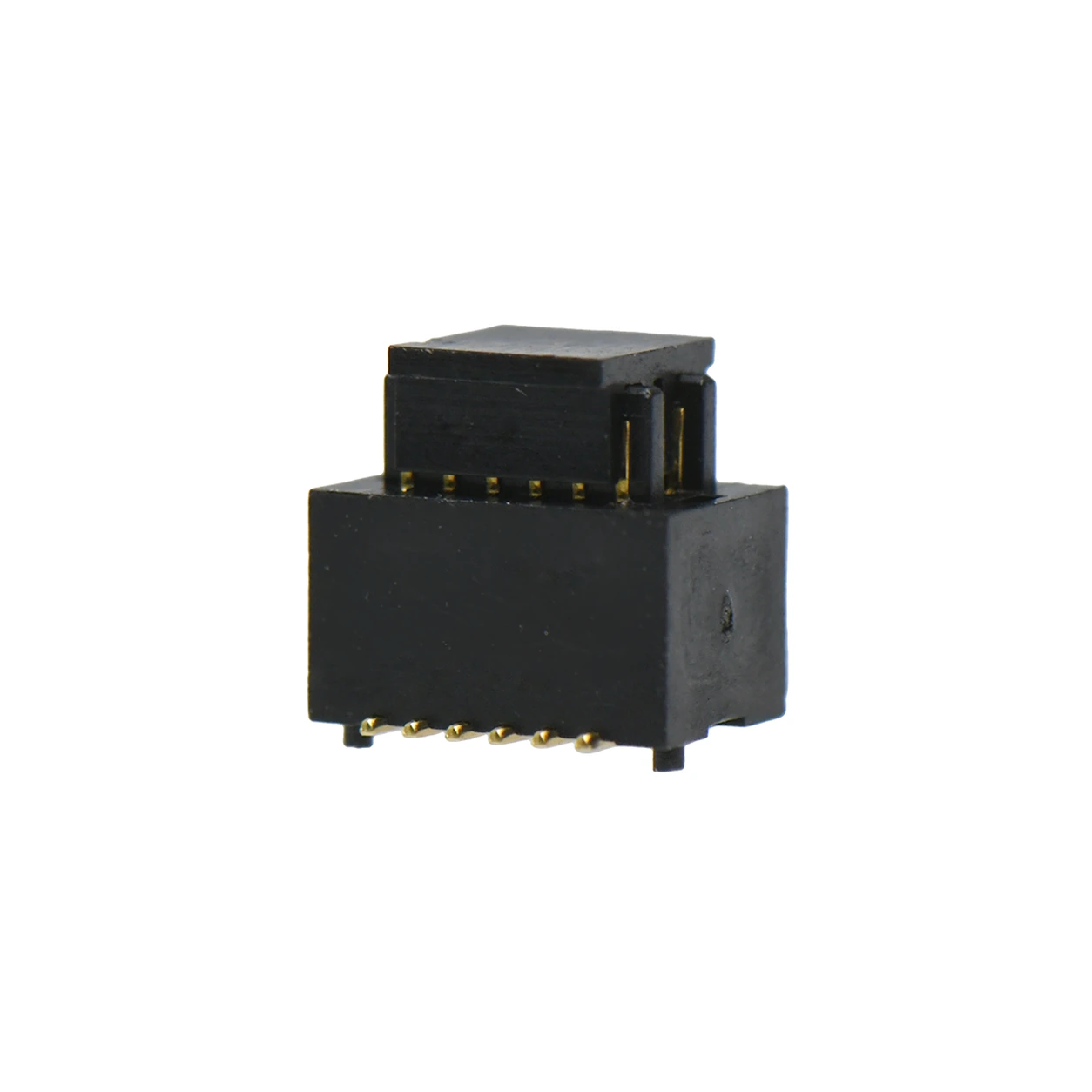
Figure: Mated male and female board-to-board connectors on a white background
Confirm Mated Height Against the PCB Stack
Mated height, also called stacking height, establishes the distance between the two PCBs after the connector pair is fully engaged. It is not merely a connector dimension; it is part of the equipment's mechanical stack.
If the mated height changes, the secondary board may sit too high or too low. That can alter enclosure clearance, screw alignment, button travel, display position, or the relationship between the PCB and nearby components. When screws or enclosure features force a mismatched stack into position, the connector, solder joints, terminals, or PCB can remain under mechanical stress.
Consider a main board connected to a small display board. Replacing the original mating pair with a different stack height may cause the display board to contact the front housing. Tightening the assembly can then bend the PCB slightly, creating an intermittent problem that appears to be an electrical fault even though the root issue is mechanical alignment.
Engineering review should compare the connector drawing with the PCB stack, enclosure geometry, mounting points, and permitted board spacing. A part that fits the footprint but changes the mated height is not a drop-in replacement.
Match Locating Features and PCB Footprints
Many board-to-board connectors include locating posts or hold-down tabs that support placement and mechanical stability. Their positions must match the PCB holes and land pattern. A visually similar connector with different post spacing may not seat on the board at all.
The solder pads also need to match the manufacturer's recommended footprint. Pad length, width, spacing, and the relationship between signal contacts and mechanical tabs affect SMT placement and reflow soldering. A mismatched land pattern can contribute to placement offset, incomplete solder joints, or uneven mechanical support.
This is why a procurement substitution should include more than a dimensional comparison from a catalog table. The review needs the connector drawing, PCB footprint, locating-hole positions, and the board-side orientation. If the PCB has already been released, the substitute must fit the existing land pattern and mechanical features without forced modification.
Move from Prototype Fit to Production Repeatability
During prototype assembly, an engineer may be able to guide two boards together by hand, adjust their angle, or shift a component slightly. Production operators cannot be expected to make a different manual correction on every unit. Any alignment dependency that requires individual adjustment becomes a repeatability risk.
Production readiness should be evaluated with the actual male and female part numbers, pitch, pin count, mated height, locating features, PCB footprints, mating direction, surrounding component heights, and enclosure clearances. A 3D interference check can identify conflicts between the connector stack and nearby mechanical features before tooling or volume assembly makes a change more expensive.
For fine-pitch, high-density, floating, or high-speed connector applications, sample fit testing becomes even more important. The engineering team should verify mating feel, board spacing, alignment, and available structure space with representative PCBs. Electrical requirements for a high-speed design also need to be confirmed from the applicable product documentation and project validation plan.
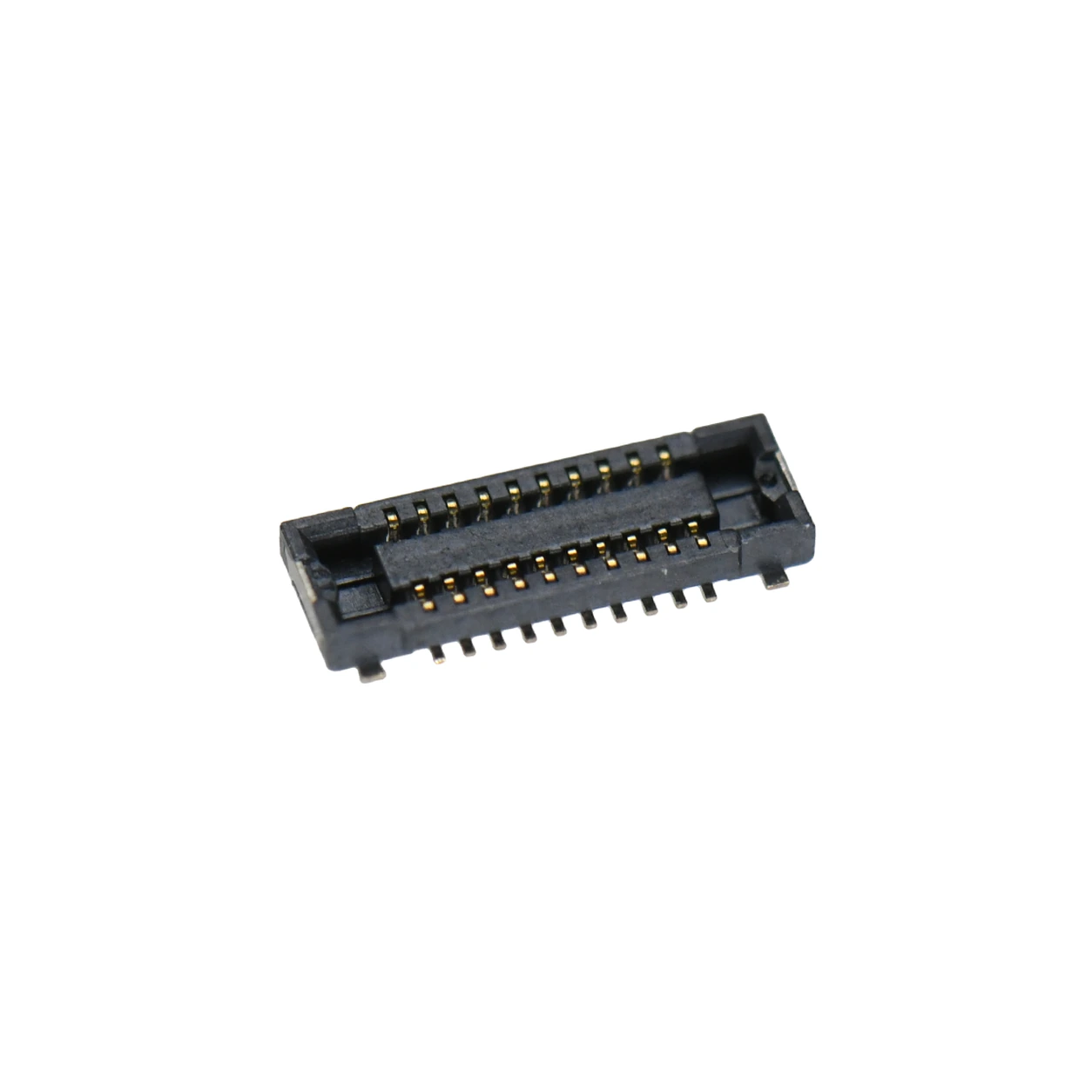
Figure: Fine-pitch surface-mount board-to-board receptacle on a white background
Divide the Verification Work Between Procurement and Engineering
Technical procurement teams can make connector selection more reliable by collecting a complete comparison package rather than searching for a loosely defined “equivalent.” The package should include the bill of materials, original manufacturer part numbers, male and female drawings, PCB footprints, application position, and available samples.
Engineering then needs to confirm that the proposed pair belongs to one mating system and fits the real PCB and enclosure stack. This review should cover the mechanical interface, board spacing, mounting features, solder-pad layout, orientation, and sample assembly result. Quality and manufacturing teams can use the same approved information to define incoming checks and assembly acceptance criteria.
Clear ownership prevents an incomplete purchasing description from becoming an engineering assumption. It also creates a traceable basis for reviewing future substitutions, PCB revisions, and supplier changes.
Board-to-Board Connector Selection Checklist
- Male connector manufacturer and complete part number
- Female connector manufacturer and complete part number
- Confirmed mating-series relationship
- Pitch and pin or position count
- Mated or stacking height
- Contact, housing-stop, and mating-depth compatibility
- Mating direction and connector orientation
- Locating-post and hold-down-tab positions
- PCB footprint and solder-pad geometry
- PCB hole locations and mounting references
- Height of surrounding components
- Enclosure, screw, display, and control clearances
- 3D mechanical interference review
- Sample fit with the actual PCB stack
- Applicable electrical and project validation requirements
- Final Selection Principle
Pitch and pin count help narrow the search, but they do not prove compatibility. A production-ready selection is a verified male-female system whose connector drawings, PCB footprints, mated height, locating features, orientation, and equipment clearances agree with the actual design.
When reviewing WLconnectivity PCB connectors, begin with the application relationship: main board to functional board, display connection, communication module, or stacked control boards. Then confirm the complete mating pair against the relevant product page, specification, drawing, PCB data, and project documentation before releasing the design or approving a substitute.