If an industrial camera begins showing corrupted images, black frames, dropped frames, or intermittent communication after months of motion, inspect three areas in order: the dynamic bend zone, the shield and return path, and the connector or termination interface. These locations fail through different mechanisms, so separating them avoids replacing a complete camera system without evidence.
Begin by preserving logs and making the symptom repeatable. Record whether the fault follows axis position, cable-carrier travel, acceleration, motor activity, temperature, or a specific connector movement. Then change one condition at a time.
A three-point diagnostic map
| Inspection point | Typical evidence | How to verify |
|---|---|---|
| Dynamic bend zone | Jacket whitening, flattening, abrasion, localized kinks, or a fault tied to carrier position | Inspect the complete travel path; log the signal while moving the axis at controlled speed |
| Shield continuity | Errors increase near drives, motors, welders, or switching equipment; symptom changes with grounding or routing | Check shield termination, bonding, routing, and controlled substitution away from interference sources |
| Connector interface | Fault reacts to connector movement, reseating, or cable load near the backshell | Inspect mating, contact condition, rear termination, strain relief, and conductor behavior under permitted movement |
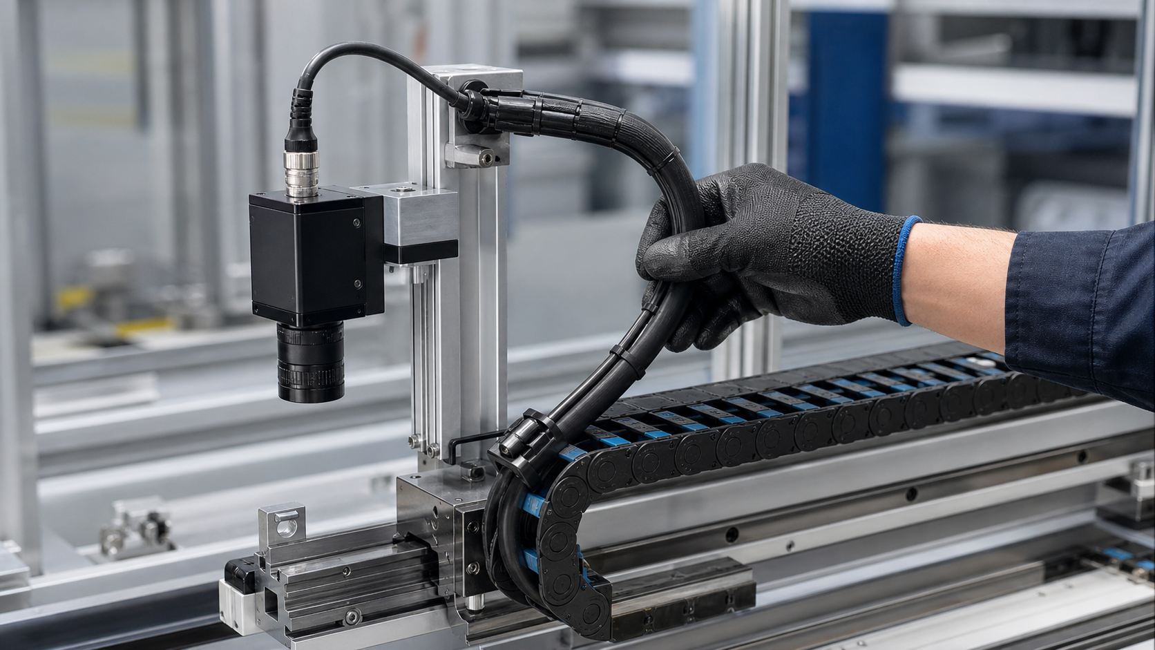
Before touching the cable: establish the failure signature
Capture camera and host diagnostics before power cycling. Depending on the interface, useful evidence can include frame counters, link resets, packet or transfer errors, trigger timing, supply voltage, and timestamps aligned with machine motion. A visually corrupted frame, a full link disconnect, and a missed trigger are different failure signatures and should not be grouped under the vague label “unstable signal.”
Create a repeatable test at reduced machine speed when possible. Record:
- the exact axis or carrier position where the symptom begins;
- whether the failure occurs in one travel direction or both;
- the effect of acceleration, speed, and dwell time;
- nearby motor, drive, solenoid, or welding activity;
- camera and cable temperature;
- whether a stationary spare cable eliminates the symptom.
Do not flex a suspect cable by hand near exposed machinery or energized conductors. Use the equipment's safe diagnostic mode and approved guarding procedure.
Check 1: the dynamic bend zone
Repeated bending can fatigue conductors, disturb pair geometry, damage insulation, separate fillers, or break shield strands. The highest-risk location is not always the center of the cable carrier. Failures often develop where the cable enters or exits the moving section, where a clamp creates a hard transition, or where a cable rubs against a divider.
Inspect the routing, not just the jacket
Look along the complete motion envelope for abrasion, crushing, twisting, jacket whitening, ripples, flattening, local swelling, and debris. Check that cables lie in the carrier without being stretched tight or forced into a smaller radius at the end brackets. Verify that the cable has enough free length to move without snaking or pushing against adjacent hoses.
The required dynamic bend radius is cable-specific. Do not apply a universal multiple to every camera cable. Use the cable manufacturer's dynamic specification, including any limits for travel distance, acceleration, temperature, and number of conductors. A cable rated for occasional flexing is not automatically suitable for continuous drag-chain motion.
Correlate the symptom with position
Run the axis through a controlled cycle while logging link status or image errors. If the fault repeatedly appears at the same carrier position, mark the corresponding physical cable section. Reverse the cable only if the installation instructions allow it; moving a fatigued section can temporarily change the symptom without repairing the damage.
Test conductors under realistic conditions
A basic continuity check can miss strands that reconnect when the cable is straight. Isolate the cable and use an approved resistance, voltage-drop, or transmission test while the suspect section moves through its allowed range. For high-speed data pairs, conductor continuity alone is insufficient because impedance balance, pair geometry, and connector termination affect performance.
Check 2: shield integrity and the EMC path
A cable can have intact signal conductors but a damaged shield braid or foil. Repeated motion may break strands near clamps and connector exits, increasing shield impedance or reducing effective coverage. The resulting errors often correlate with motor switching, servo operation, variable-frequency drives, or other electromagnetic sources.
Inspect both the cable construction and the way the shield is terminated. A high-coverage shield provides limited benefit if it is connected through a long pigtail where a low-impedance circumferential termination is required. Conversely, changing the bonding scheme without understanding the system can create unwanted current paths.
Controlled checks for suspected interference
- Temporarily route a known-good cable away from high-current and switching cables while maintaining safe separation and bend limits.
- Compare operation with the nearby drive or actuator inactive, if the process permits.
- Verify the enclosure bonding, connector shell contact, and shield termination against the machine EMC design.
- Inspect for corrosion, paint, loose hardware, or contamination at bonding surfaces.
- Use the camera interface vendor's approved cable or link test rather than relying only on a multimeter.
Do not disconnect protective earth or improvise shield connections on operating equipment. Any bonding change should be reviewed within the electrical safety and EMC design.
Check 3: connector contacts, termination, and strain relief
Motion at the cable can be transferred into the connector if the rear clamp is loose, the bend begins too close to the backshell, or the connector body is used as a cable support. That load can stress solder joints, crimps, insulation displacement points, and contact retention features.
De-energize the system and inspect:
- complete mating and correct key alignment;
- locking-thread or coupling engagement;
- bent, recessed, contaminated, or worn contacts;
- looseness between the connector body and panel;
- cable movement inside the backshell or overmold;
- sharp bends at the connector exit;
- damaged jacket, seal, or strain-relief component.
Clean contacts only with the approved method. Do not use abrasives on plated surfaces. If a field-terminable connector is involved, check conductor preparation, shield termination, contact insertion, and assembly torque against the controlled work instruction. For molded cable assemblies, visible looseness, intermittent behavior, or insulation damage generally calls for replacement and failure analysis rather than field disassembly.
Distinguish cable failure from camera, power, and software issues
The cable is a strong suspect when the fault follows a specific bend position or disappears with a known-good stationary assembly. It is not the only possibility. Verify the camera supply at the load, host-port behavior, trigger wiring, acquisition settings, firmware compatibility, network configuration where applicable, and thermal conditions.
A useful substitution sequence is:
- keep the camera and host unchanged; replace only the cable with a verified compatible assembly;
- keep the verified cable; test the original camera on a known-good port or host;
- compare the original host port with another approved port;
- restore one original item at a time until the symptom returns.
Document each configuration. Simultaneously replacing the camera, cable, and host may resume production but leaves the root cause unknown.
Specify the next cable assembly from the motion profile
For a moving camera application, provide more than length and connector type. A cable-assembly supplier needs the communication interface, data rate, power conductors, pinout, shielding and grounding scheme, connector orientation, required environmental protection, cable-carrier dimensions, dynamic bend radius, travel distance, speed, acceleration, temperature, chemical exposure, and expected duty cycle.
Review connector options for vision equipment under M12 connectors for machine vision. When routing, pinout, labeling, shielding, or test requirements are application-specific, define them as part of custom wire harnesses before assembly begins.
Preventive design and maintenance checklist
- Select a cable explicitly rated for the intended continuous-flex or torsional motion.
- Keep the cable within its specified dynamic bend radius through the full travel.
- Separate moving cables with suitable carrier dividers and avoid overfilling.
- Provide strain relief without creating a rigid, high-stress bend transition.
- Keep signal cables away from high-current switching paths where the design requires separation.
- Validate shield and bonding continuity after assembly.
- Test the complete camera link through representative motion, acceleration, temperature, and electrical noise.
- Trend link errors or dropped frames so degradation is visible before an unplanned stop.
Final takeaway
Repeated-bend camera faults become easier to solve when the inspection follows the physical failure path. First locate the dynamic bend section, then verify the shield and EMC path, and finally inspect the connector and termination. Align camera logs with machine motion, substitute one verified component at a time, and specify the replacement assembly from the actual movement and electrical environment.