Choose a rear-nut receptacle when a simple center cutout is important and the back of the panel remains accessible for installation, tightening, and service. Choose a square-flange receptacle when the design benefits from a clear anti-rotation load path, front-side fastener access, and multiple mounting points—and when the panel can accommodate the center opening plus four accurately positioned holes.
Neither style is universally better. The correct choice depends on panel geometry, rear clearance, insertion and withdrawal forces, vibration, sealing, assembly sequence, service access, and the exact connector drawing.
The fundamental difference is the panel load path
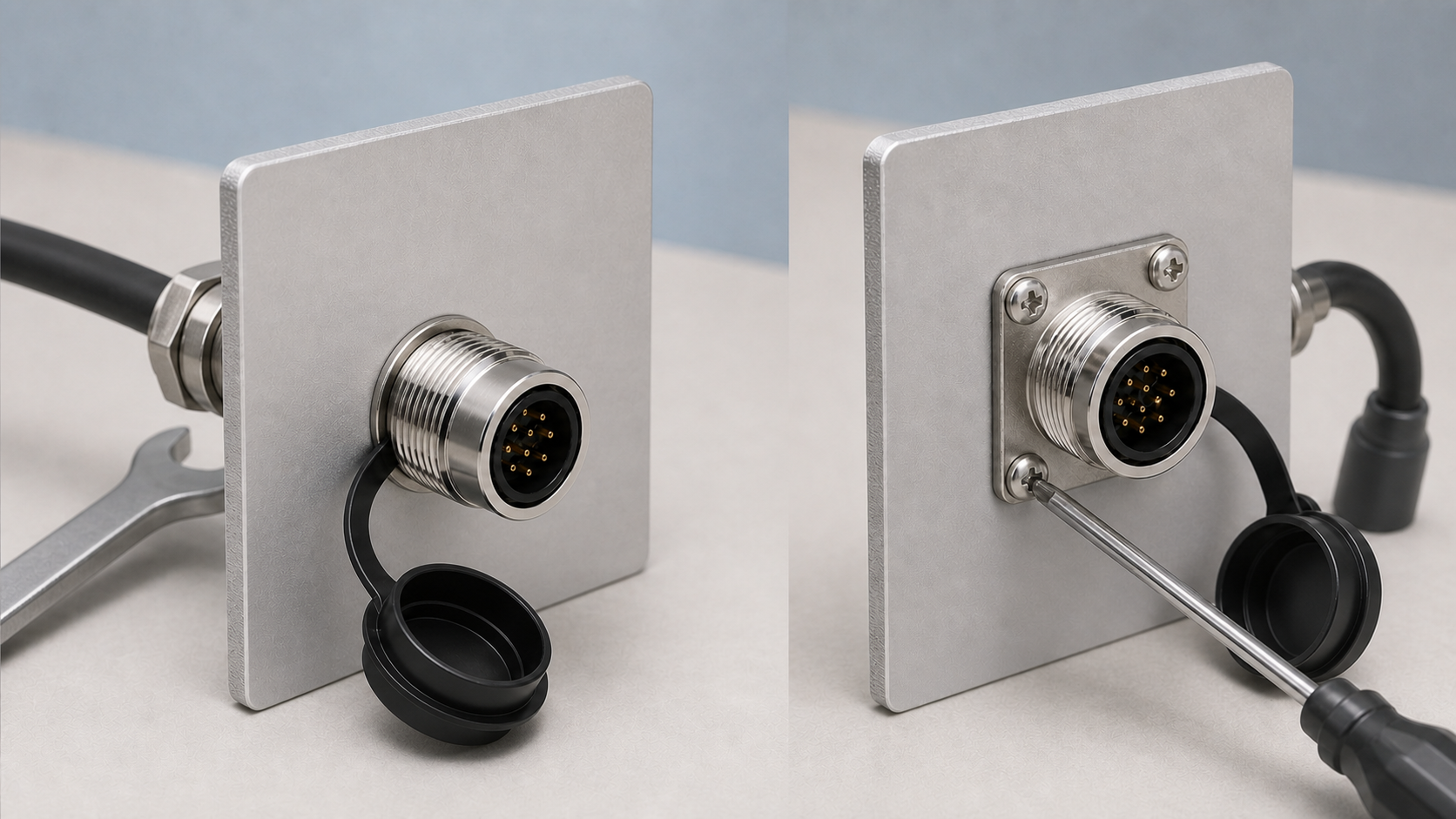
A rear-nut receptacle passes through a center opening and is secured by a nut from the back of the panel. The cutout can be relatively simple, but the design must reserve space for the nut, wiring, tools, and a technician's hand. The assembly may also need a positive anti-rotation feature when the mating connector transmits torque to the receptacle.
A square-flange receptacle uses four fasteners around the connector body. The fasteners establish a distributed mounting pattern and resist rotation through the flange and panel. “Square flange” describes the mounting base; it does not normally mean that the panel needs a square opening. The center cutout, four mounting holes, locating details, and seal geometry must come from the drawing for the complete part number.
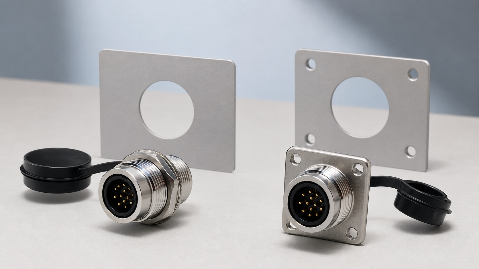
Side-by-side engineering comparison
| Decision factor | Rear-nut receptacle | Square-flange receptacle |
|---|---|---|
| Panel machining | Typically centered on one main cutout; anti-rotation details may still be required | Center opening plus four mounting holes and their positional tolerances |
| Assembly access | Requires rear access for nut and tools | Mounting fasteners may be managed from the front, depending on hardware |
| Anti-rotation | Depends on nut preload and any dedicated locating feature | Four-point pattern provides a direct panel constraint |
| Rear envelope | Must accommodate the nut, wiring, bend radius, and service tools | Still requires room for termination and cable routing, even if screws are front-accessible |
| Fastener control | One rear nut, with specified torque and locking method where required | Four fasteners, with torque sequence and loosening control where required |
| Service implications | Difficult if boards or harnesses block the rear nut | Flange removal may be easier from the front, but rear terminations still need access |
When a rear-nut receptacle is the stronger candidate
Prioritize a rear-nut design when most of the following conditions are true:
- the panel benefits from a simple primary cutout;
- the rear of the panel is accessible during both production and field service;
- there is enough clearance for the nut, socket or wrench, conductors, and cable bend;
- insertion, withdrawal, and twisting loads are modest or controlled;
- the drawing includes an adequate anti-rotation method for the expected torque;
- the assembly process can verify nut torque and retention.
The machining may be simpler, but the total assembly is not automatically cheaper. A difficult nut location can add labor, special tools, inspection time, and service risk. Model the internal envelope before the panel drawing is released.
When a square-flange receptacle is the stronger candidate
Prioritize a square-flange design when the application needs a clearly defined anti-rotation path or accessible panel fasteners, and the following conditions can be met:
- the panel has room for the flange and four-hole pattern;
- the hole positions and panel flatness can be controlled;
- the assembly process can manage four fasteners and any locking hardware;
- the panel material and thickness can carry the local fastener loads;
- the seal has an adequate, continuous compression surface;
- rear space remains available for wiring and termination service.
A flange can distribute mounting loads and make the retention scheme visible, but it adds holes and fasteners. Thin panels may need washers, backing features, inserts, or reinforcement. Confirm this through mechanical analysis and first-article testing rather than assuming that four screws always improve durability.
Vibration and repeated mating: evaluate loads, not labels
A mating-cycle specification describes repeated connection and disconnection under stated conditions. It does not by itself prove that the panel mount will resist the application's vibration or repeated operator torque.
Map the forces in both directions:
- The operator or automated tool applies insertion, withdrawal, and twisting forces at the mating interface.
- The connector body transfers those forces into the rear nut or flange.
- The mount transfers them into the panel around the cutout and fasteners.
- The cable and termination add their own static and dynamic loads behind the panel.
For a rear-nut design, verify nut preload, anti-rotation behavior, and access for retightening or inspection. For a flange, verify fastener preload, torque sequence, panel deformation, loosening control, and load sharing. Test the finished panel assembly with the actual mating cable, not only an isolated receptacle.
Sealing depends on the complete interface
An ingress-protection rating for a connector family does not automatically carry over to every installation. Both mounting styles require the correct cutout, a flat and clean sealing surface, compatible gasket or O-ring material, correct compression, proper mating, and a sealed rear termination where applicable.
Check for paint buildup, burrs, weld distortion, scratches, gaps across panel seams, and fastener patterns that warp the flange. For a rear-nut mount, make sure tightening does not rotate or damage the seal. For a flange mount, use the required tightening sequence so the gasket is compressed evenly.
Part-number and drawing control prevent expensive mistakes
Do not select the mounting style from a cropped model number or a product photo. Similar contact arrangements may be offered in cable plugs, rear-nut receptacles, and flange receptacles. For example, DF12J410 is a straight cable plug rather than a rear-nut receptacle, illustrating why the complete part number matters.
Before release, procurement and engineering should agree on:
- complete manufacturer part number and mating part number;
- contact arrangement, keying, and pin assignment;
- panel cutout and hole-position tolerances;
- panel thickness, finish, and sealing surface;
- mounting hardware, torque, and locking method;
- rear clearance, termination method, and cable bend envelope;
- environmental and mechanical validation requirements.
Review the mounting variants within DF series aviation connectors, then compare the broader aviation plug connector options if the panel architecture is not yet fixed.
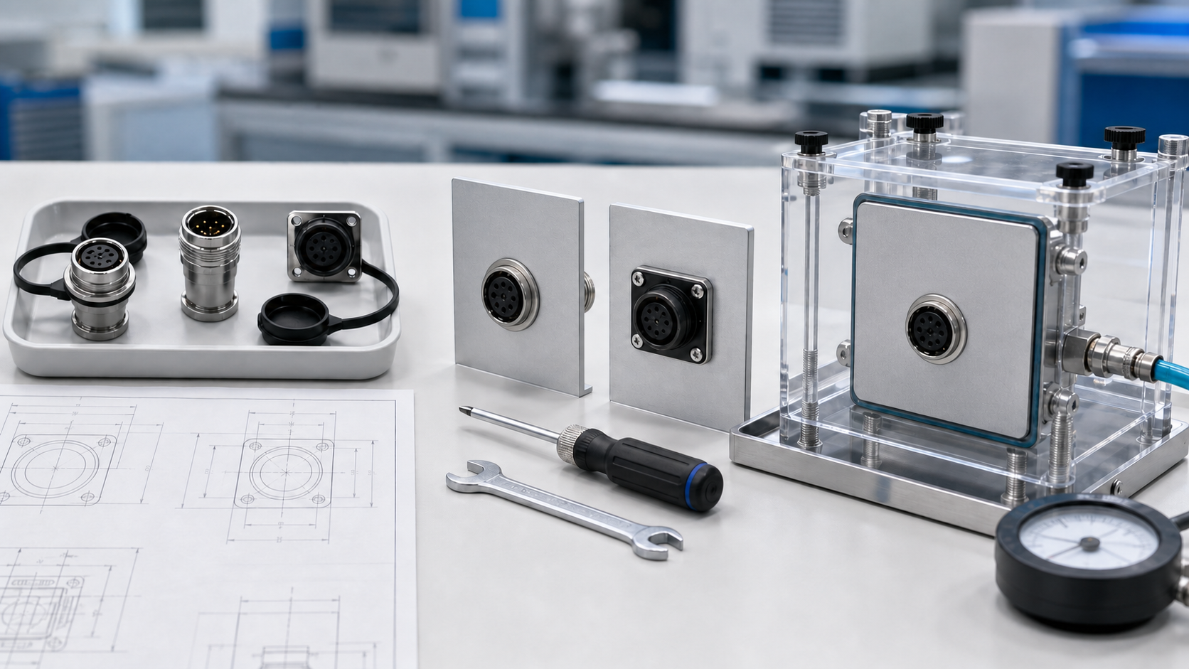
First-article validation checklist
- Inspect all cutout edges and hole locations against the controlled drawing.
- Confirm that the receptacle seats without forcing, rocking, or seal damage.
- Apply and record the approved fastener or nut torque.
- Mate and unmate the production plug while observing panel and receptacle movement.
- Verify internal clearance at the worst cable bend and component tolerance.
- Perform the required ingress, vibration, and mechanical tests on the assembled panel.
- Repeat removal and replacement using the intended service procedure.
Final takeaway
The decision is not “round hole versus square flange.” It is a choice between two load paths and two service strategies. Define panel access, mating loads, vibration, sealing, internal clearance, and maintenance before choosing the receptacle. Then lock the decision to the complete part number, controlled drawing, and a tested first-article assembly.