Do not set an M12 panel cutout from the mating-interface name alone. “M12” often describes the circular mating interface, while the panel-mount thread may be M12×1.0, M16×1.5, PG9, or another size. The correct cutout comes from the dimensioned drawing for the complete receptacle part number, including its front-lock or rear-lock construction, anti-rotation feature, seal geometry, allowable panel thickness, and tolerances.
A reliable workflow is: identify the exact mounting thread, derive a preliminary clearance from the drawing, check how the seal contacts the panel, confirm usable thread engagement at the finished panel thickness, and validate the first manufactured panel with the actual connector.
Quick decision sequence
- Confirm the complete connector and mating-part numbers.
- Identify front-lock or rear-lock mounting and the direction of assembly.
- Read the panel thread, shoulder diameter, flats or key, and cutout dimensions from the controlled drawing.
- Check the seal location and required compression surface.
- Calculate the finished cutout after paint, plating, anodizing, or other coating.
- Verify that the finished panel thickness falls inside the specified mounting range.
- Trial-fit and test a first article before releasing production tooling.
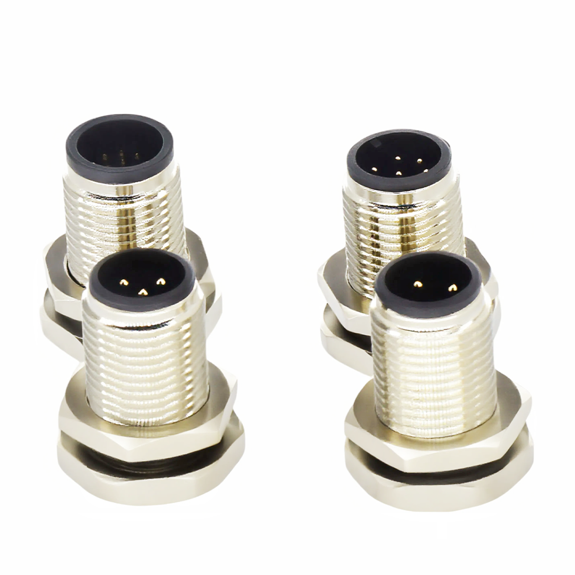
First identify the mounting style
Front-lock panel mounting
In a front-lock design, the receptacle is inserted from one side of the panel and the retaining hardware is accessible from the front. This can simplify final assembly when the back of the enclosure is crowded, but the flange, nut, or locking feature may occupy visible panel space. Confirm which components sit on each side; product terminology is not always consistent across suppliers.
Rear-lock panel mounting
A rear-lock design uses retaining hardware behind the panel. It may provide a cleaner front face, but the enclosure must leave room for the nut, tool, termination, and cable bend. Service access should be checked in the assembled machine, not only in the empty enclosure.
Both styles may use the same nominal mating interface and still require different panel openings. Never copy a cutout from a visually similar receptacle.
The mating thread is not necessarily the mounting thread
The M12 designation commonly refers to the coupling interface presented to the mating cable connector. The panel-retention thread is a separate feature. This product range includes several mounting-thread families:
| Mounting thread | Drawing or cutout reference | Typical selection context |
|---|---|---|
| M12×1.0 | Often described as an M12 panel cutout | Compact standard mounting-thread option |
| M16×1.5 | Often described as an M16 panel cutout | Larger mounting body or reinforced panel interface |
| PG9 | PG9 cutout reference | Product variants using the PG thread system |
This table helps identify the right drawing; it is not a machining specification. The exact hole may include clearance, flats, a keyway, a D-shape, locating holes, or a shoulder that prevents rotation. Use the drawing dimensions and tolerance scheme for the complete part number.
Turn the mounting thread into a controlled cutout
For a simple round clearance hole, the finished opening must be large enough for the threaded body to pass through without damaging the threads or coating, yet small enough to preserve the required support and sealing surface. One product-specific example uses 12.2 mm for an M12×1.0 mounting thread, with a ±0.1 mm example tolerance.
Treat 12.2 mm as an example, not a universal rule. The correct value depends on:
- actual maximum thread or shoulder diameter;
- runout and manufacturing tolerance of the connector body;
- panel-hole process capability and burr allowance;
- coating thickness and buildup at the edge;
- required anti-rotation geometry;
- available seal land around the opening;
- any relevant company or equipment design standard.
The drawing should define the finished condition. If laser cutting, punching, or machining occurs before coating, specify whether the tolerance applies before or after the finish. Inspect the finished part using a method that detects ovality and local coating buildup, not only one diameter reading.
Check how the seal engages the panel
Many panel receptacles use an O-ring or gasket between a connector shoulder or flange and the panel face. In this arrangement, the seal is compressed axially against the panel rather than sealing on the cutout wall. The hole must still preserve a continuous, flat sealing land.
Review the section view and confirm:
- which side of the panel carries the seal;
- the seal material and chemical compatibility;
- the required surface finish and flatness;
- the distance from the cutout edge to the seal contact band;
- whether paint, labels, welds, seams, or fasteners interrupt that band;
- the specified torque or assembly position that establishes compression.
Do not assume that tightening harder improves the seal. Excessive torque can extrude the gasket, deform a thin panel, damage the receptacle, or reduce thread life. Use the assembly instruction for the exact product.
Panel thickness determines usable thread engagement
The panel consumes part of the available mounting-thread length. A panel that is too thick may leave insufficient thread for the retaining nut. A panel that is too thin may prevent the nut or shoulder from clamping the assembly, especially if the design reaches a mechanical stop before the panel is compressed.
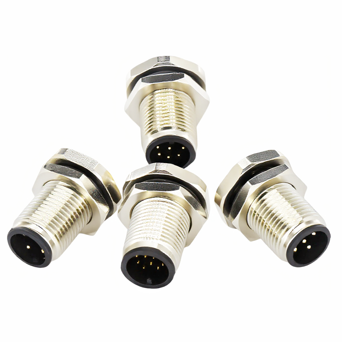
The M12XXX-03-201-M12 front-lock solder-cup example specifies a 1–5 mm panel range. That range belongs to this configuration and should not be transferred to other M12 receptacles without checking their drawings.
For the selected part, verify:
- minimum and maximum finished panel thickness;
- available thread length after the panel, washer, seal, and any anti-rotation plate are included;
- required number of engaged threads or nut position;
- clearance for solder cups, PCB pins, pigtails, or an overmold;
- wrench access and cable bend space;
- panel stiffness under mounting torque and mating loads.
If the existing panel is outside the allowed range, use an approved spacer, reinforcement, alternate part, or extended-thread variant only when the supplier drawing supports it.
Do not confuse the panel cutout with the cable-entry range
Some panel connectors include a rear cable gland or pigtail. Its cable outside-diameter range is a separate selection parameter. One PG7 cable-entry example specifies a 4–6 mm cable range. It does not determine the panel cutout.
Verify the rear cable diameter, seal option, strain relief, and bend radius independently. A correct panel hole cannot compensate for a mismatched cable gland, and a correctly sealed cable entry cannot compensate for a damaged panel gasket.
Drawing requirements for production
A production panel drawing should state more than a nominal hole label. Include, as applicable:
- finished cutout diameter and tolerance;
- locating flat, keyway, D-shape, or anti-rotation feature;
- true-position tolerance relative to adjacent controls or connectors;
- finished panel thickness and material;
- coating and masked sealing areas;
- burr direction and edge-break requirements;
- surface flatness or finish in the seal land;
- mounting orientation and datum reference;
- controlled connector drawing and revision.
These details prevent a shop from interpreting “M12 hole” as a generic 12 mm opening.
First-article validation before volume production
1. Inspect the finished cutout
Measure diameter, shape, location, burrs, and coating condition. Confirm that the connector passes through without forcing or excessive radial play.
2. Assemble with production hardware
Use the intended seal, washer, nut, tool, and torque method. Confirm that the flange or shoulder sits evenly and that the seal remains in position.
3. Check the full internal envelope
Install the termination, PCB, or cable and verify electrical clearance, tool access, minimum bend radius, and service access. A receptacle that fits the bare panel may still conflict with the finished assembly.
4. Mate the actual cable connector
Verify key alignment, coupling access, mating torque where applicable, and panel movement under insertion and withdrawal loads.
5. Run application-level tests
Perform the required ingress, insulation, vibration, temperature, and functional tests on the complete assembly. An IP67 or IP68 component rating should not replace validation of the installed enclosure interface.
Browse M12 connector options to compare mounting constructions, or review the wider M12 circular connector range before finalizing the mating and panel interfaces.
Final takeaway
The safest M12 cutout is the one controlled by the exact receptacle drawing and verified in the finished panel. Separate the mating interface from the mounting thread, evaluate the seal land, include coatings and tolerances, confirm usable thread length at the actual panel thickness, and prove the design with a complete first-article assembly.