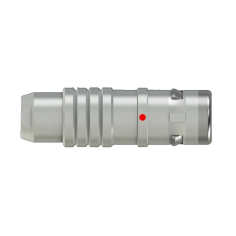
K Series Push-Pull Self-Locking Connectors
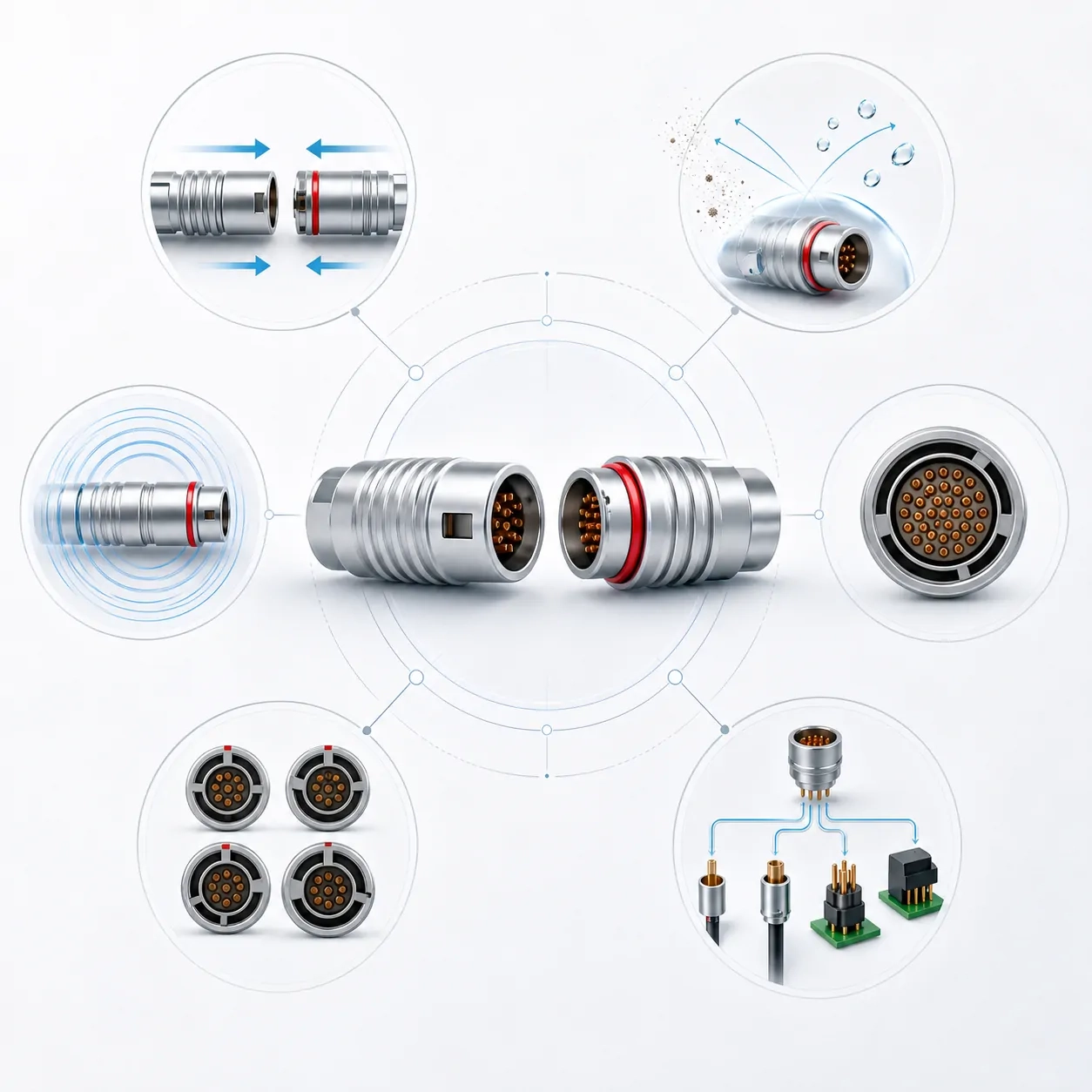
Key Features
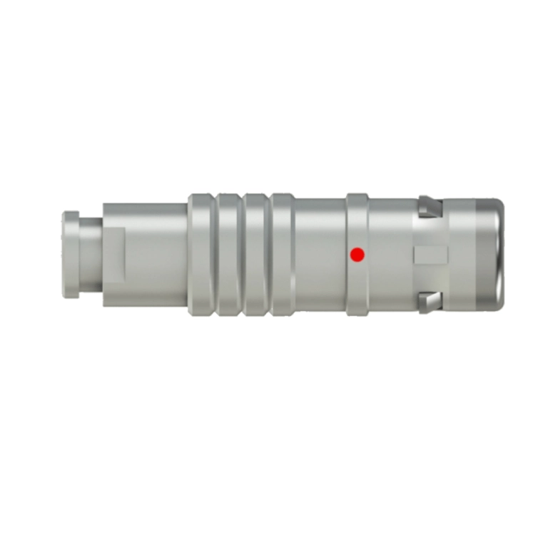
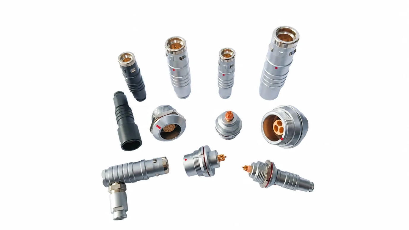
Type of K-Series Receptacles
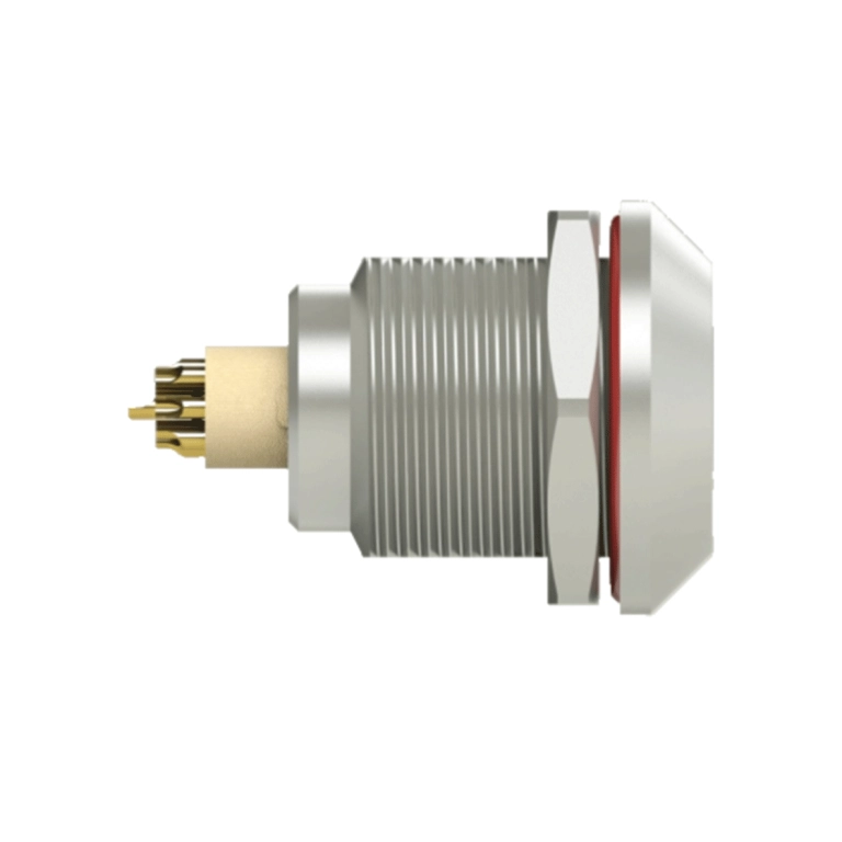
K Series ZGG Fixed Receptacle — Front-Panel Mount with Mounting Nut
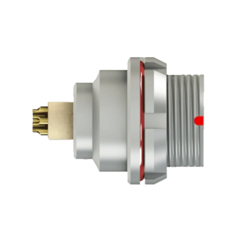
K Series ZEG Fixed Receptacle — Rear-Panel Mount with Mounting Nut
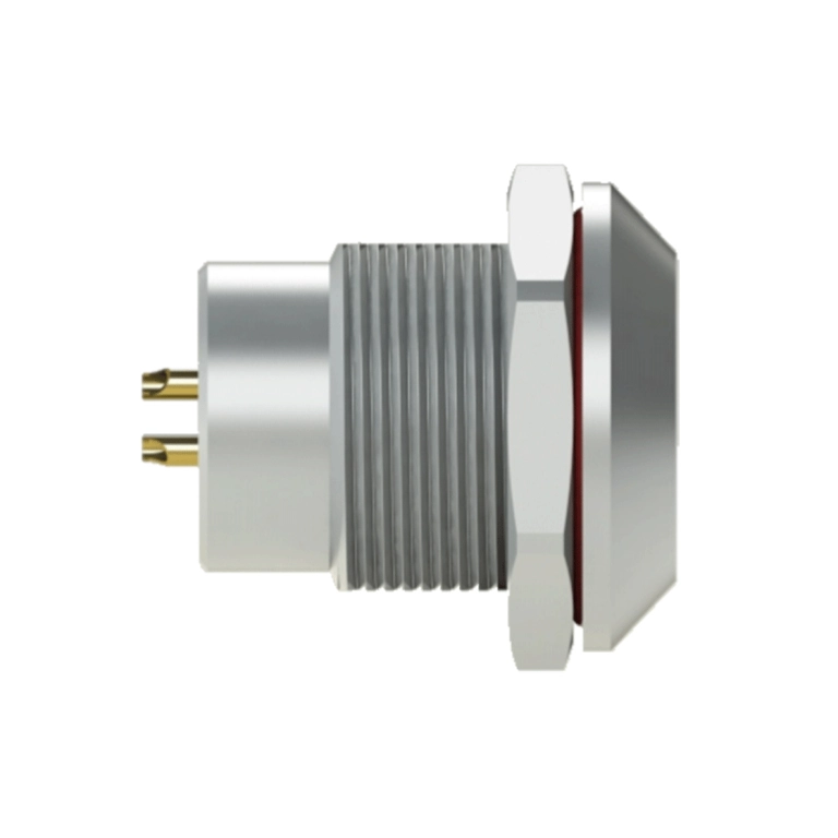
K Series MGG Fixed Receptacle — Front-Panel Mount with Mounting Nut, Watertight/Vacuum-Tight
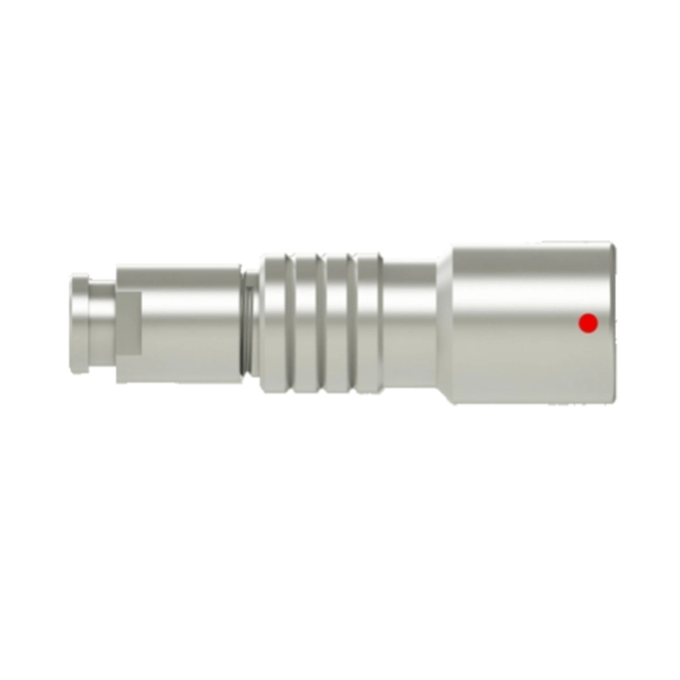
K Series DHG Cable-Mount Free Receptacle — Cable Collet and Nut for Fitting a Bend Relief
K Series Plug Assembly Instructions
Exploded view of the K Series plug, showing the component sequence and key alignment points for cable assembly.
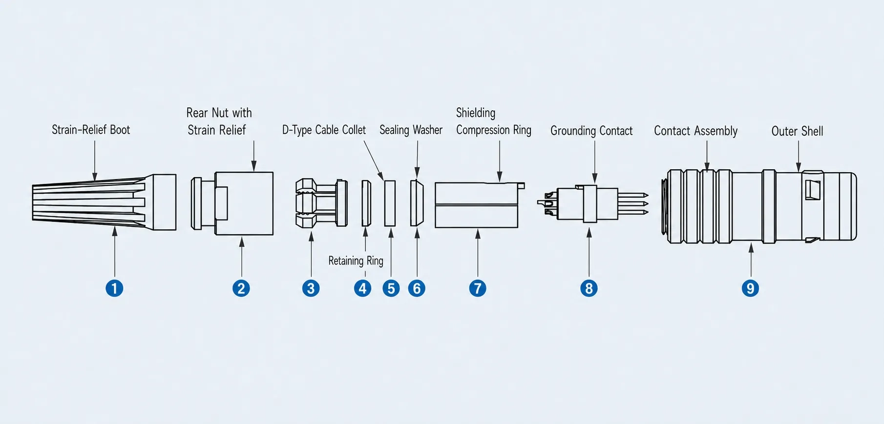
1)Pass the cable sequentially through the protective boot ①, rear nut ②, cable clamp ③, V-shaped gasket ④, cable seal ⑤, and shield crimp ring ⑥.
Then solder the conductors to the corresponding pins of the insulator assembly ⑦ in the correct order.
2)Fit the insulator retaining ring ⑦ onto the insulator assembly ⑧, ensuring that the projection on the retaining ring aligns with the notch in the insulator assembly. Then slide the shield crimp ring ⑥, cable seal ⑤, V-shaped gasket ④, and cable clamp ③ into their proper positions in sequence. Ensure that the intact outer jacket of the cable extends into the shield crimp ring ⑥.
3)Insert the assembled insulator assembly into the plug assembly ⑨, ensuring that the notch on the insulator retaining ring ⑦ aligns with the projection inside the plug assembly ⑨.
4)Screw the rear nut ② onto the plug assembly ⑨ and tighten it securely.
5)Fit the protective boot ① over the rear nut ②.
K Series Technical Features
Item | Specification |
|---|---|
| Mating Cycles | >5,000 cycles |
| Humidity | Up to 95% RH at 60°C |
| Temperature Range | -45°C to +125°C |
| Vibration | 10–2,000 Hz, 15 g |
| Shock | s* |
| Salt Spray Resistance | >72 h |
| Ingress Protection Rating | IP65–IP68 |
Need Help Choosing the Right Connector?

K Series Cable Harness Assembly Guide
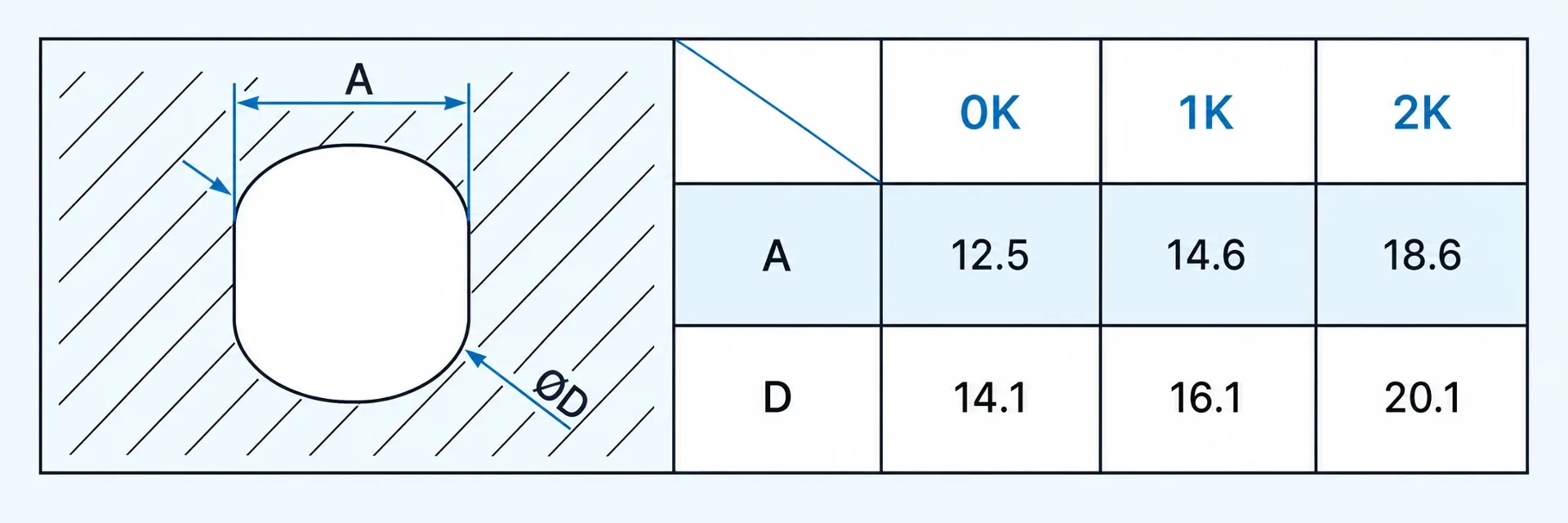
Recommended panel cutout dimensions for mounting the K Series connector. All dimensions are in millimeters.
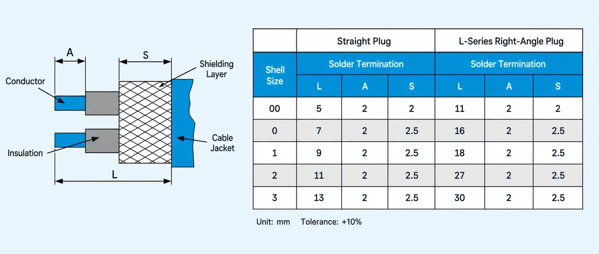
Exploded view showing the assembly sequence and correct positioning of the K Series cable harness components.
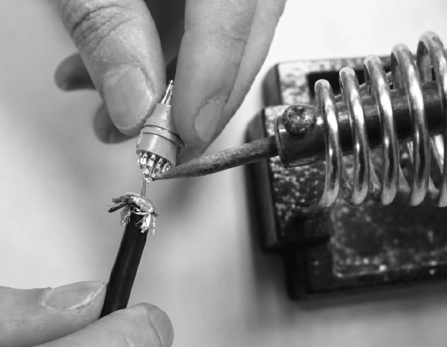
Soldering Guidelines
✦ The cable outer diameter must match the size of the cable clamp.
✦ The conductor size must match the termination diameter of the pin contact.
✦ For lead-free soldering, the soldering iron temperature should be maintained at approximately 380°C.
✦ The soldering time for each conductor must be less than 1 second.
✦ After soldering, each individual conductor must be insulated with heat-shrink tubing.
✦ Take care to protect the pin contacts and insulator during soldering.