In a compact robotic joint, fitting the connector through the housing is only the beginning. The plug body, cable exit, bend radius, service hand space, strain-relief point, and joint motion envelope all compete for the same limited volume. A connector selected by shell diameter alone can force a late housing change, overbend the cable, or leave technicians unable to disconnect the joint without dismantling surrounding hardware.
The DS28 24-pin circular connector can consolidate multiple circuits at a joint boundary, but the engineering value comes from how the interface is integrated. Mechanical clearance, pin assignment, electromagnetic compatibility, cable construction, termination workmanship, and maintenance strategy must be designed together.
Use a 24-pin connector in a compact robot joint when the pin count, electrical ratings, signal mix, physical envelope, and maintenance plan all support a single modular interface. Compare straight and right-angle cable exits in the actual 3D assembly, separate noisy power paths from sensitive feedback signals in the pin map, define shielding and grounding, and verify the finished cable assembly on a moving prototype. A high contact count saves space only when it does not create a new EMC, thermal, routing, or service-access problem.
The Real Constraint Is Behind the Connector
A CAD model that shows only the panel receptacle hides most of the installation volume. The mated plug extends into or away from the joint, the cable needs a controlled exit, and the harness requires a fixed point before joint movement can transfer force into the termination. Tool access and the removal path add another layer of clearance.
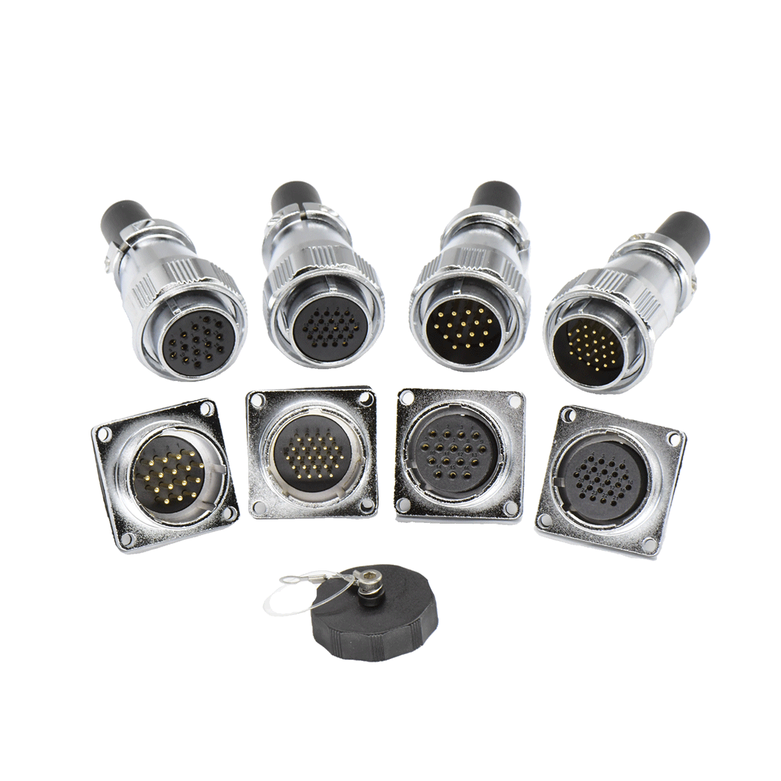
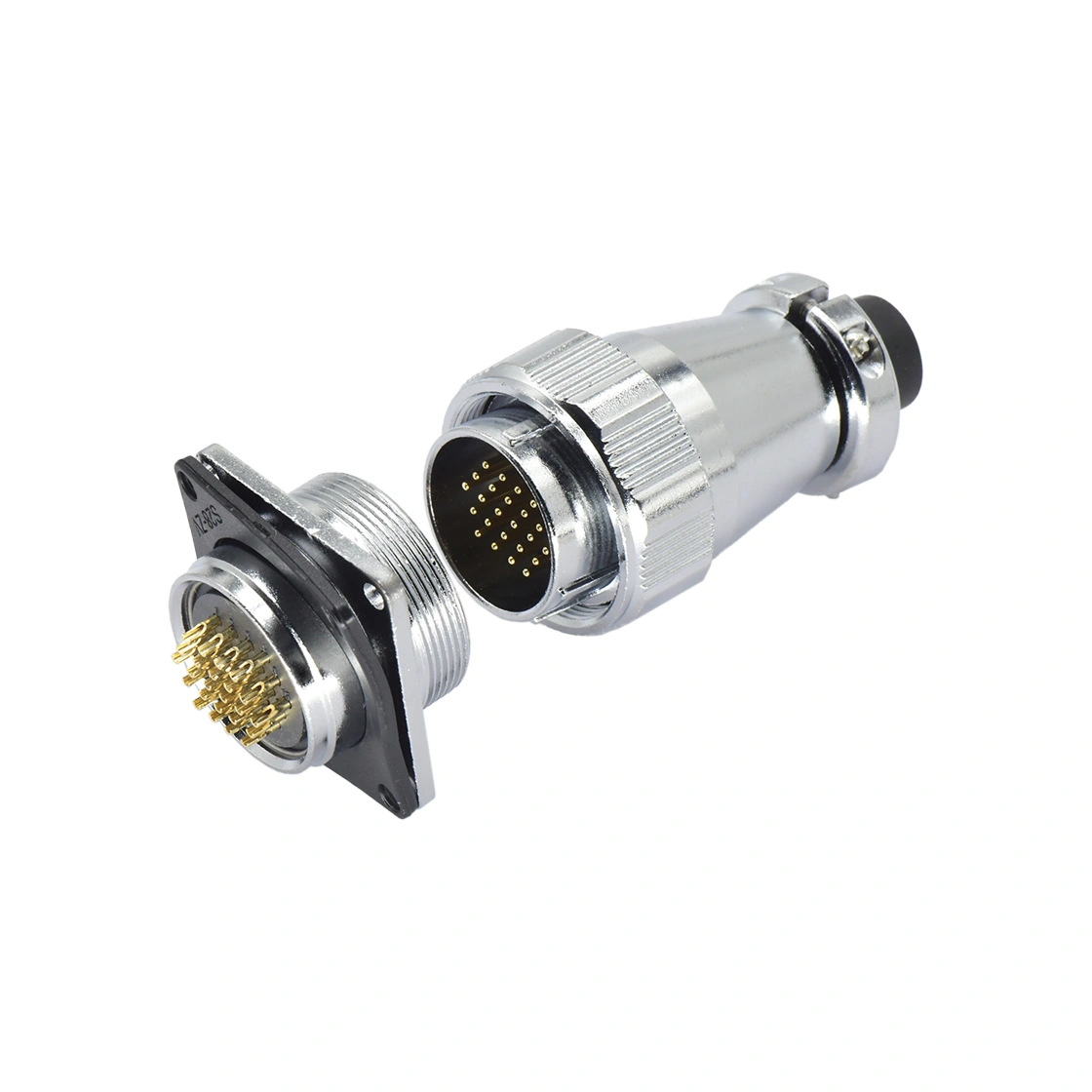
Straight cable exits work well when axial depth is available and the service path follows the connector centerline. They also make the mating direction easy to understand. However, the design must reserve the full plug length, coupling area, cable boot, bend transition, and hand space.
Right-angle exits can reduce rearward depth when the cable must immediately follow a housing wall or enter a nearby routing channel. Their orientation is more sensitive. Rotating the receptacle or elbow by a small amount can direct the harness toward a rib, bearing, motor, or moving link. The angle therefore has to be fixed in the assembly definition, not left to the installer.
Check the Entire Motion Envelope
Robot-joint routing is a dynamic problem. The harness may twist, flex, or change its distance from adjacent structures throughout the axis range. A cable that clears the housing at the home position can rub or tighten at another angle. The 3D review should therefore include the plug, receptacle, boot, cable diameter, minimum bend radius, clamp position, moving envelope, and the path required for replacement.
The first fixed point after the connector matters. If it is too far away, movement loads can reach the contacts or solder joints. If it is too close, the cable may be forced into a sharp transition. A representative harness should be installed on the prototype so the team can observe twist accumulation, surface contact, clamp behavior, and connector access through repeated motion.
Freeze the Interface with a Joint-Specific Verification Gate
A production-ready decision needs more than a successful fit check. Before the joint housing is released, assemble one evidence package that links the 3D clearance review, controlled pin map, current budget, harness drawing, termination instruction, and service-removal method. This makes the connector boundary auditable when the motor, sensor set, cable, or housing later changes.
Run the verification on a representative joint with the production-intent cable exit, clamp locations, and protective parts installed. Exercise the planned motion range and operating modes while monitoring continuity and the signals most likely to reveal intermittent behavior. Record cable contact, twist accumulation, connector temperature where relevant, locking condition, and the time and tools needed to remove the module. Acceptance limits should come from the robot program; a catalog rating is not a substitute for this installed test.
The procurement boundary should also be exact. A replacement with the same shell size and contact count is not automatically equivalent if keying, contact gender, cable exit, conductor range, termination, or sealing differs. Any substitution should return to engineering for drawing comparison and a decision on which validation evidence must be repeated.
A 24-Pin Interface Needs a Signal Plan
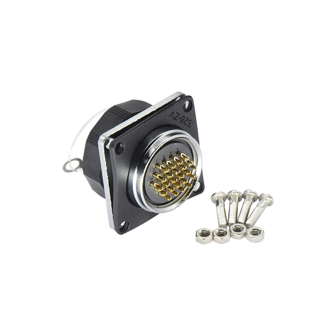
The DS28 family includes variants with 8, 10, 12, 20, and 24 contacts and straight or 90-degree cable exits. The 24-pin version can bring encoder feedback, limit switches, torque sensing, I/O, and other joint circuits through one physical boundary.
Consolidation reduces the number of separate connectors, but it does not make unlike circuits electrically compatible. A pin-assignment document should identify each circuit, voltage class, current, return path, shield, spare, and maintenance function. Sensitive encoder or sensor conductors should not be placed beside switching or motor-related conductors without an EMC review.
For the 24-pin DS28 configuration, specified limits include 5 A rated current, 400 V AC working voltage, a one-minute withstand voltage of 1,200 V AC, 5 mΩ contact resistance, 2,000 MΩ insulation resistance, and conductors no larger than 0.75 mm² or 18 AWG. These figures establish component limits; they do not mean every contact may carry its maximum simultaneously inside a confined joint. Temperature rise, conductor bundling, duty cycle, adjacent-contact loading, and the finished assembly must be assessed for the actual circuit map.
Design Shielding and Grounding Before the Harness Drawing Freezes
Electromagnetic compatibility is often the decisive issue when power, feedback, and I/O share one connector. The engineering package should state which pairs are twisted, which circuits are shielded, how shields terminate, whether the connector shell participates in the shield path, and where bonding occurs.
A high insulation-resistance value does not address coupling between adjacent conductors. Good EMC performance depends on circuit grouping, pair geometry, cable construction, termination length, shield continuity, grounding topology, and routing relative to motors and switching devices. These decisions should be tested under realistic motor operation rather than checked only with the robot unpowered.
Termination workmanship is equally important. Soldering or other termination methods, heat-shrink placement, cable identification, shield preparation, and strain relief should be controlled by a documented process. A visually tidy connector can still contain uneven joints, long untwisted sections, or unsupported conductors that become intermittent under motion.
Verify Materials Against the Operating Environment
The DS28 family uses gold-plated copper contacts, a chrome-plated zinc-alloy shell, a PPS insulator, and threaded locking. Specified limits include a −40°C to +85°C operating range and 500 mating cycles. These features can support an industrial interface, but suitability depends on the complete application.
Oil mist, cleaning fluids, humidity, conductive dust, washdown, temperature cycling, and repeated flexing may affect the cable jacket, sealing parts, shell finish, and termination differently. The required ingress-protection level should be confirmed for the exact mated assembly and installation. If the joint is frequently disconnected, the maintenance-cycle estimate should include actual service frequency and handling conditions rather than relying on nominal connector life alone.
Turn the Joint into a Replaceable Module
The strongest reason to consolidate a joint interface is service architecture. When all required power, feedback, limit, and control circuits cross a documented connector boundary, the joint can become a separately tested module. Production can validate the module before installation, and service teams can isolate faults without re-terminating individual conductors inside the robot.
That result depends on configuration control. Pin numbering, connector gender, key orientation, cable labels, spare-contact policy, torque requirements, and electrical tests must remain consistent across the robot, spare joint, and service harness. A change to one circuit should trigger a review of drawings, assembly instructions, test fixtures, and replacement stock.
At WLconnectivity, we recommend that teams configuring a DS aviation connector evaluate the full mating system and cable exit rather than selecting by shell size alone. Where the connector is part of a finished moving assembly, a cable assembly for robotics can integrate conductor selection, pinout, shielding, routing, labeling, termination, and testing into one controlled deliverable.
Prototype and Release Checklist
- Confirm every circuit, return, shield, spare, and current path in the pin map.
- Check simultaneous current loading and temperature rise for the actual duty cycle.
- Compare straight and right-angle exits in the complete 3D joint model.
- Reserve mating, locking, tool, hand, bend, clamp, and removal clearance.
- Simulate or physically check the entire joint-motion envelope.
- Define twisted pairs, shielding, shell bonding, and grounding.
- Control termination, heat-shrink, identification, and strain relief.
- Verify the exact part-number drawing, ratings, materials, sealing, and mating life.
- Test continuity, insulation, shield continuity, signal integrity, motion durability, and service removal on representative hardware.
- Confirm that production and spare modules use the same controlled interface definition.
Use Contact Count to Simplify the System
A 24-pin connector should make the robot easier to build, verify, and maintain—not merely place more circuits in one shell. When mechanical access, motion routing, electrical separation, termination quality, and service documentation are designed as one boundary, the DS28 interface can support a compact, replaceable joint module. If any of those elements remain undefined, the high-density connector can simply move complexity into a smaller and harder-to-reach space.