A waterproof connector can meet an IP67 or IP68 product rating and still leak after installation if the cable entry is assembled incorrectly. The rear gland is a system: the gland nut applies force, the clamping fingers transfer that force, and the elastomer seal must compress evenly around a cable with the correct outside diameter. A mismatch, damaged seal, insufficient tightening, excessive tightening, or an immediate sharp bend can create a path for water.
When moisture appears behind the connector, begin with the cable outside diameter and rear-clamp condition. Then inspect the seal, gland nut, cable routing, temperature exposure, and the other possible ingress paths before replacing the complete connector.
How the cable-entry seal works
Most rear glands use compression rather than adhesive. Tightening the rear nut drives a clamping element against an elastomer seal. The seal deforms radially and presses against the cable jacket. The assembly must perform two jobs at the same time:
- maintain continuous seal contact around the cable jacket;
- restrain the cable so pull and bending loads do not reach the conductors or terminations.
If the cable is too small, the seal may reach its deformation limit before it grips the jacket. If it is too large, assembly may cut, fold, or extrude the seal, or leave too little thread engagement. Neither condition should be corrected with improvised tape, filler, or uncontrolled force.
First check: match the actual cable outside diameter
Measure the finished cable, not the nominal conductor size. Jacket tolerances, shielding, braid, fillers, and supplier differences can change the outside diameter. Measure an undamaged, uncompressed section with calipers. Rotate the cable and check more than one position because some cables are not perfectly round.
The DP family specifies the following cable outside-diameter ranges. Use them as selection references only; verify the exact connector suffix, seal option, drawing, and current product specification before ordering or assembly.
| Connector size | Cable range I | Cable range II |
|---|---|---|
| DP11 | 3–4 mm | 4–6.5 mm |
| DP13 | 4–6.5 mm | 5–8 mm |
| DP17 | 7–10 mm | Not listed |
| DP21 | 4.5–7 mm | 7–12 mm |
| DP29 | 9–13 mm | 13–16 mm |
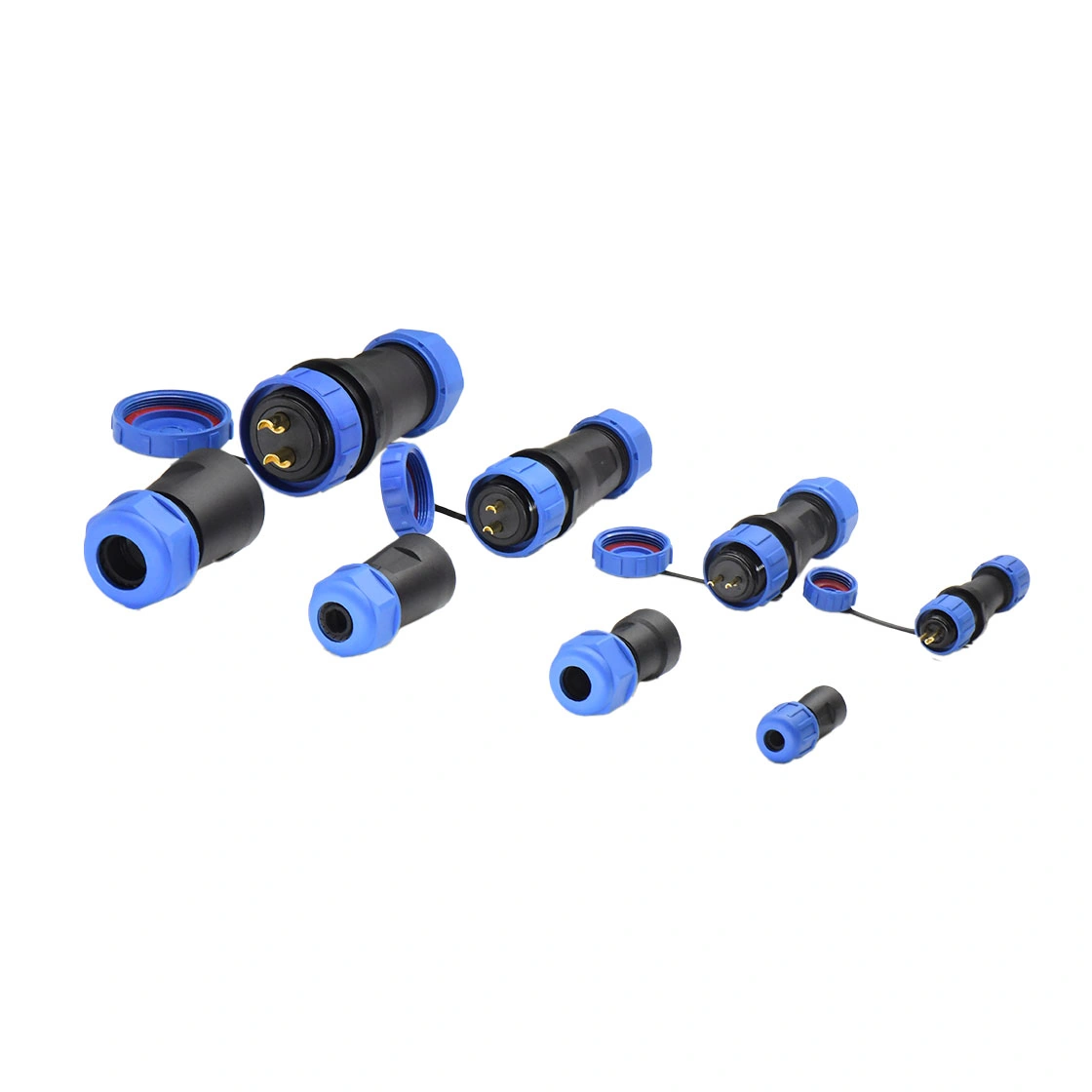
What happens when the cable is too small?
The seal may not develop enough radial compression, leaving a narrow annular gap between the jacket and elastomer. Water, coolant, humid air, and fine contamination can migrate through that gap. A small leak can also lower insulation resistance over time without producing an immediate short circuit.
What happens when the cable is too large?
Forcing an oversized cable through the gland can tear or roll the seal, distort the clamping element, damage the jacket, or prevent the nut from reaching adequate thread engagement. The assembly may initially look tight but relax or loosen after temperature cycling and vibration.
Second check: verify the clamping and tightening path
Correct cable diameter is necessary but not sufficient. The gland nut, threads, clamping fingers, and seal must be installed in the correct order and remain undamaged.
Incomplete tightening
A hand-tightened nut may stop because of thread contamination, cross-threading, a misplaced seal, or cable torsion rather than correct compression. Compare the assembled position with the product instructions and apply only the specified torque. If the manufacturer does not publish a torque, request it rather than inventing a value.
Excessive tightening
More torque does not always improve sealing. Excessive force can crack a polymer body, strip threads, displace the seal, or cut the cable jacket. Replace damaged parts; do not continue tightening in an attempt to recover a compromised interface.
Damaged or uneven clamping fingers
Clamping fingers that are cracked, permanently deformed, or assembled off-center cannot apply uniform pressure. Inspect every finger and the seal contact pattern after disassembly. Uneven impressions on the cable jacket can indicate asymmetric loading.
A bend that begins at the gland exit
A sharp bend immediately behind the nut pulls the cable to one side. That side load can disturb seal contact and concentrate fatigue at the termination. Provide a straight exit length and external cable support before the cable enters its required bend. Use the cable and connector manufacturers' bend-radius rules rather than a universal multiplier.
Seal condition and environmental compatibility
An elastomer can harden, swell, crack, or lose recovery after exposure to temperature cycling, ultraviolet light, oil, cleaning chemicals, or coolant. Dust and grit can also score the sealing surface during assembly. Check the material against the actual environment and inspect for:
- cuts, nicks, flattening, or permanent compression set;
- swelling, stickiness, hardness, or discoloration;
- debris on the cable jacket or seal surface;
- jacket seams, printing ridges, or damage crossing the sealing zone;
- missing, doubled, twisted, or incorrectly seated components.
Use only compatible lubricants if the assembly instructions call for lubrication. An unapproved lubricant may attack the elastomer, change friction, or cause the seal to move during tightening.
Do not overlook temperature-driven moisture movement
Outdoor and enclosed equipment heats during operation and cools after shutdown. Pressure changes can draw humid air through a marginal seal, and the moisture may later condense inside the housing. This “breathing” effect can make a leak appear intermittent or unrelated to rain.
Check every boundary of the enclosure, including panel seals, mating interfaces, vents, cable glands, covers, and condensation control. Finding water near the cable entry does not prove that it entered there; trace deposits, corrosion patterns, and test results before concluding.
A safe, repeatable leak-investigation sequence
- De-energize the equipment and document the connector orientation, cable routing, and visible moisture before disassembly.
- Measure the cable outside diameter in multiple orientations and compare it with the exact part-number range.
- Check gland-nut position, thread engagement, cross-threading, and any specified torque record.
- Disassemble according to the instructions and inspect the clamp, seal, jacket, and component order.
- Confirm that the cable exits straight and is externally supported.
- Inspect the mating seal and panel interface so another ingress path is not missed.
- Replace damaged sealing parts and repeat the specified ingress or pressure test on a representative assembly.
Do not perform an improvised powered water test. Use the product's defined test method, equipment safety procedure, and acceptance criteria.
Selection information to send a connector supplier
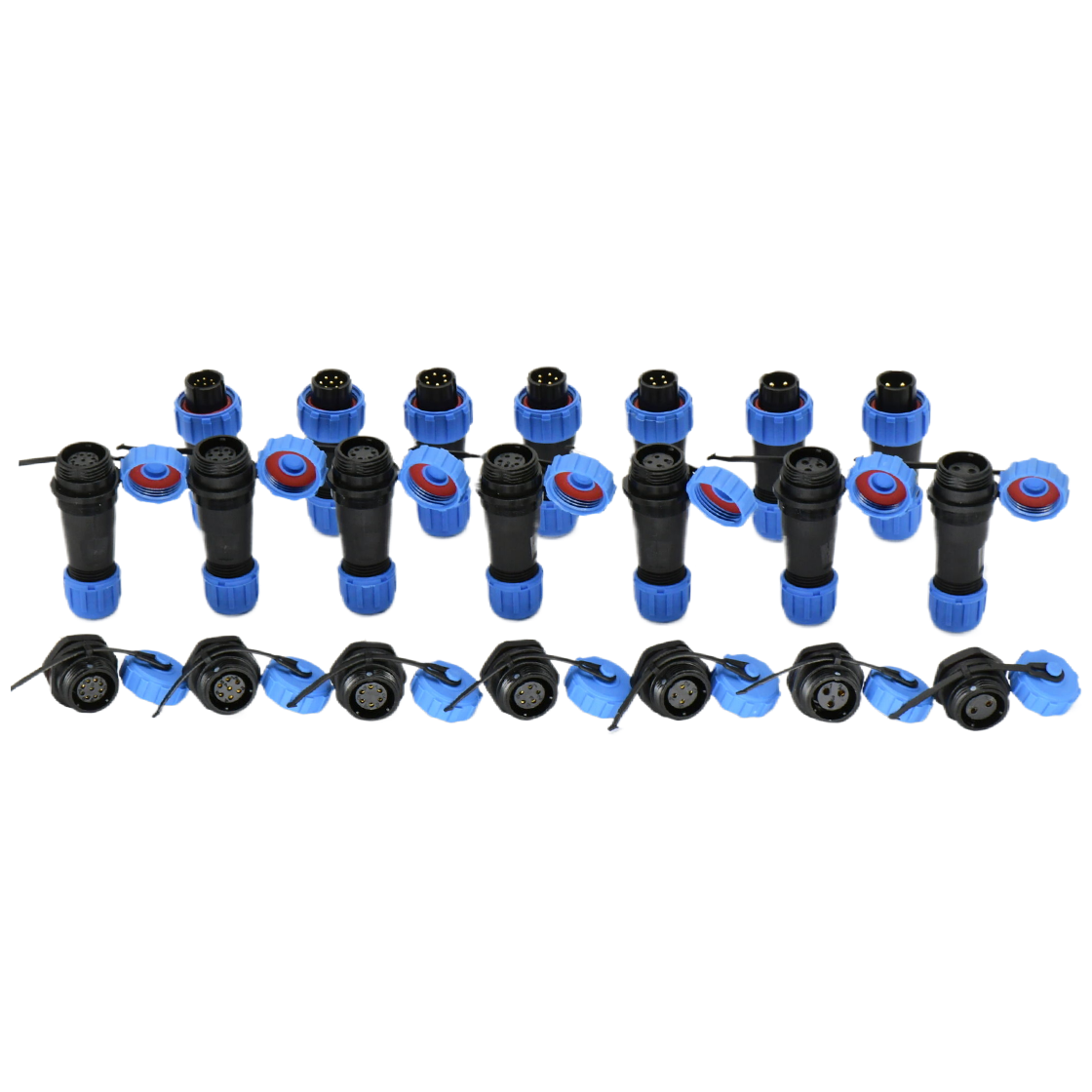
Provide the full cable outside-diameter range, jacket material, static or dynamic routing, temperature range, fluids and chemicals, required ingress protection, panel geometry, mating frequency, and expected vibration. If several cables are approved for production, verify each one rather than selecting from an average diameter.
For these size options and cable ranges, review DP series aviation connectors and confirm the drawing and seal option for the complete part number.
Final takeaway
Rear-entry leaks are usually solved by treating the gland as a controlled mechanical system. Match the real cable diameter, preserve even seal compression, follow the specified tightening method, support the cable, and validate the finished assembly under the relevant environmental conditions.