F Series Push-Pull Self-Locking Connectors
Key Features
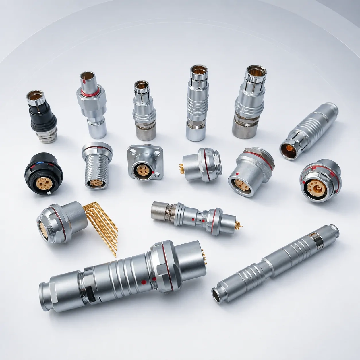
F Series Plug Types
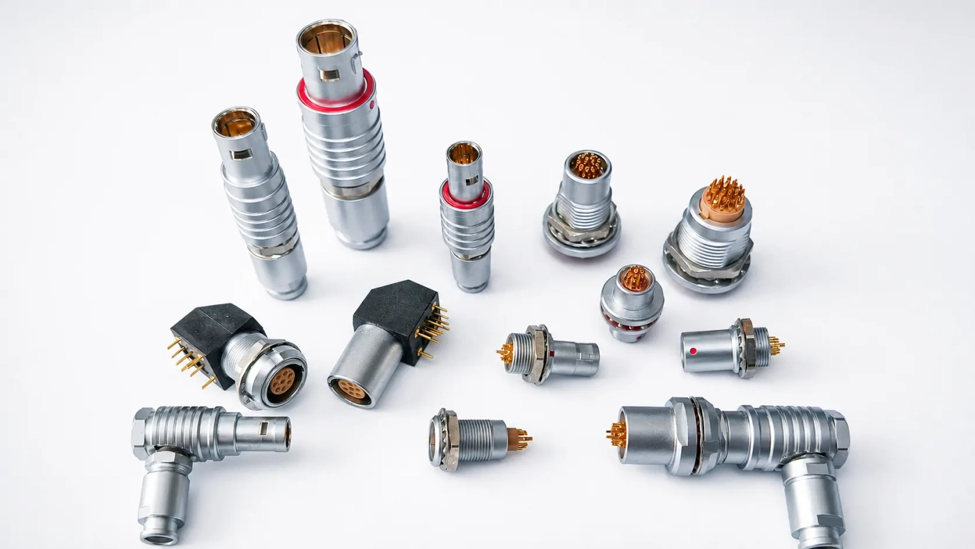
F Series Receptacle Types
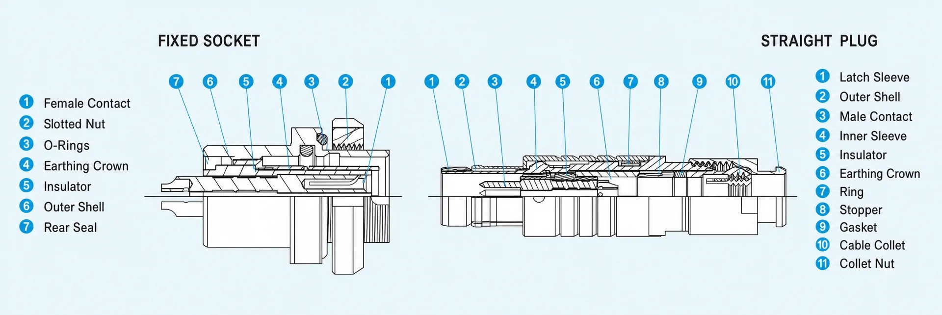
F Series Product Cross-Sectional View
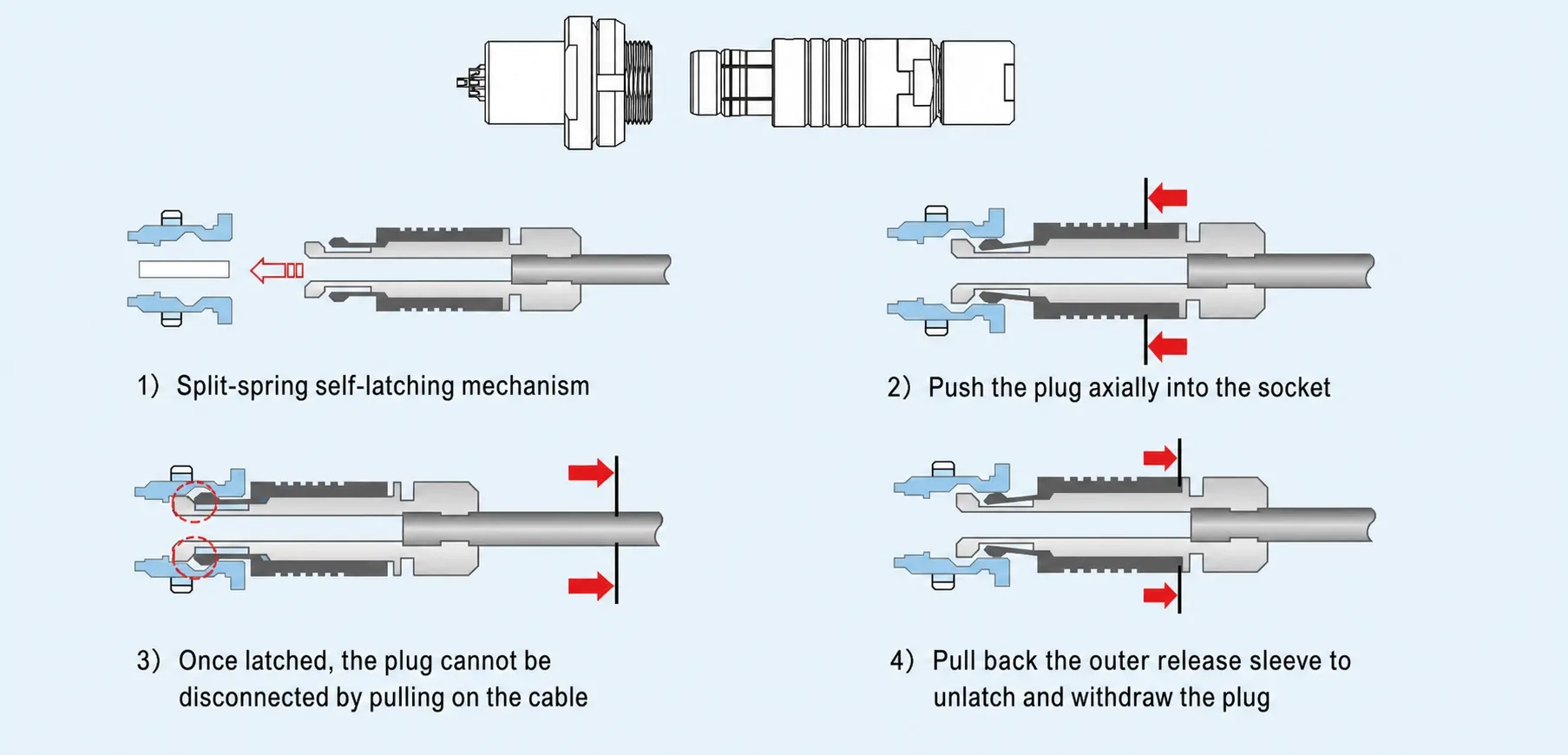
F Series Self-Locking Configuration Illustrations
F Series Technical Features
Parameter | Specification |
|---|---|
| Mating Cycles | >5,000 cycles |
| Humidity | Up to 95% RH at 60°C |
| Temperature Range | -55°C to +145°C |
| Vibration | 10–2,000 Hz; acceleration: 147 m/s²; contact discontinuity: ≤1 μs |
| Shock | Acceleration: 490 m/s²; contact discontinuity: ≤1 μs |
| Salt Spray Resistance | Pearl chrome: 72 h; black nickel: 96 h; 316L stainless steel: 1,000 h |
| Ingress Protection Rating | IP68, waterproof and dustproof |
Need Help Choosing the Right Connector?

F Series Plug Assembly Instructions
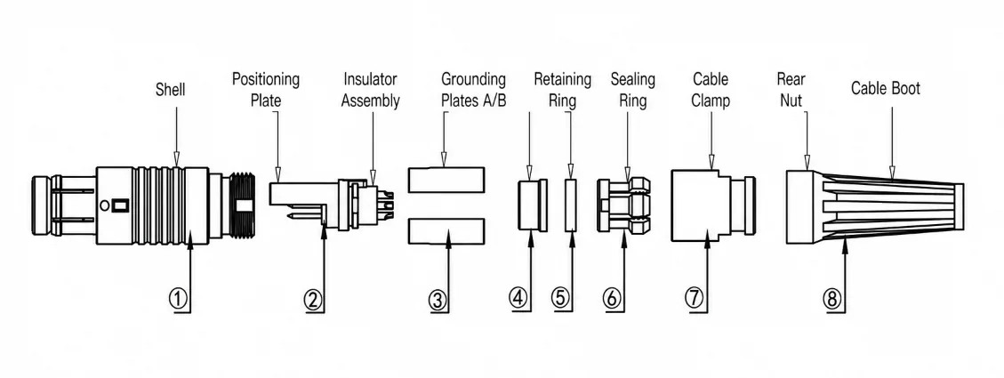
1)Feed the cable through the cable boot ⑧, rear nut ⑦, cable clamp ⑥, sealing ring ⑤, and retaining ring ④ in sequence. Then solder the conductors to the insulator assembly ② according to the specified wiring sequence.
2)Fit grounding plates A/B ③ onto the soldered insulator assembly ②. Make sure the projection on the insulator assembly ② aligns with the notch in the grounding plates ③. Then slide the retaining ring ④, sealing ring ⑤, and cable clamp ⑥ into their proper positions on the cable.
3)Insert the assembled cable clamp ⑥, sealing ring ⑤, retaining ring ④, grounding plates A/B ③, and insulator assembly ② into the plug housing assembly ①.
4)Screw the rear nut ⑦ onto the plug housing assembly ① and tighten it securely.
5)After confirming that the assembly passes the dielectric withstand voltage, insulation resistance, and cable flex tests, fit the cable boot ⑧ over the corresponding shoulder on the rear nut ⑦.
Short-Body Plug Assembly Instructions
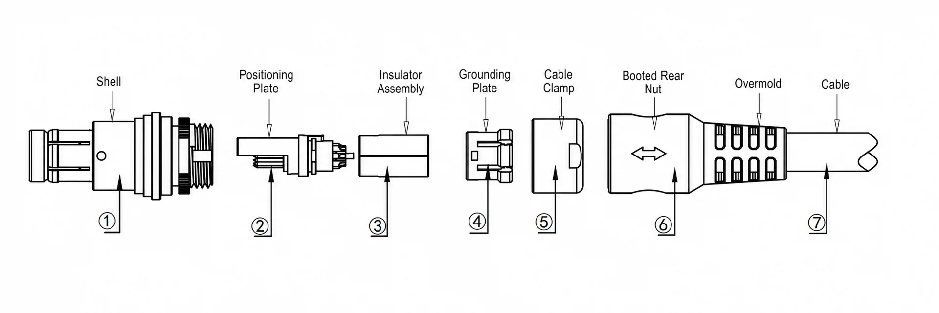
1)Feed the cable through the rear nut ⑤ and cable clamp ④ in sequence. Then solder the conductors to the insulator assembly ② according to the specified wiring sequence.
2)Fit the grounding plate ③ onto the soldered insulator assembly ②. Make sure the projection on the insulator assembly ② aligns with the notch in the grounding plate ③. Then slide the cable clamp ④ into its proper position on the cable.
3)Insert the assembled cable clamp ④, insulator assembly ②, and grounding plate ③ into the plug housing assembly ①.
Screw the rear nut ⑤ onto the plug housing assembly ① and tighten it securely.
4)After confirming that the assembly passes the dielectric withstand voltage, insulation resistance, and cable flex tests, place it in the molding machine for final overmolding.
F Series Cable Harness Assembly Guide
Cable Harness Preparation
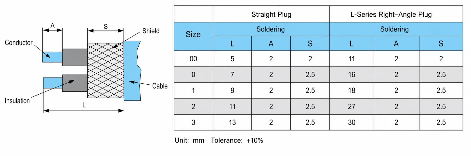
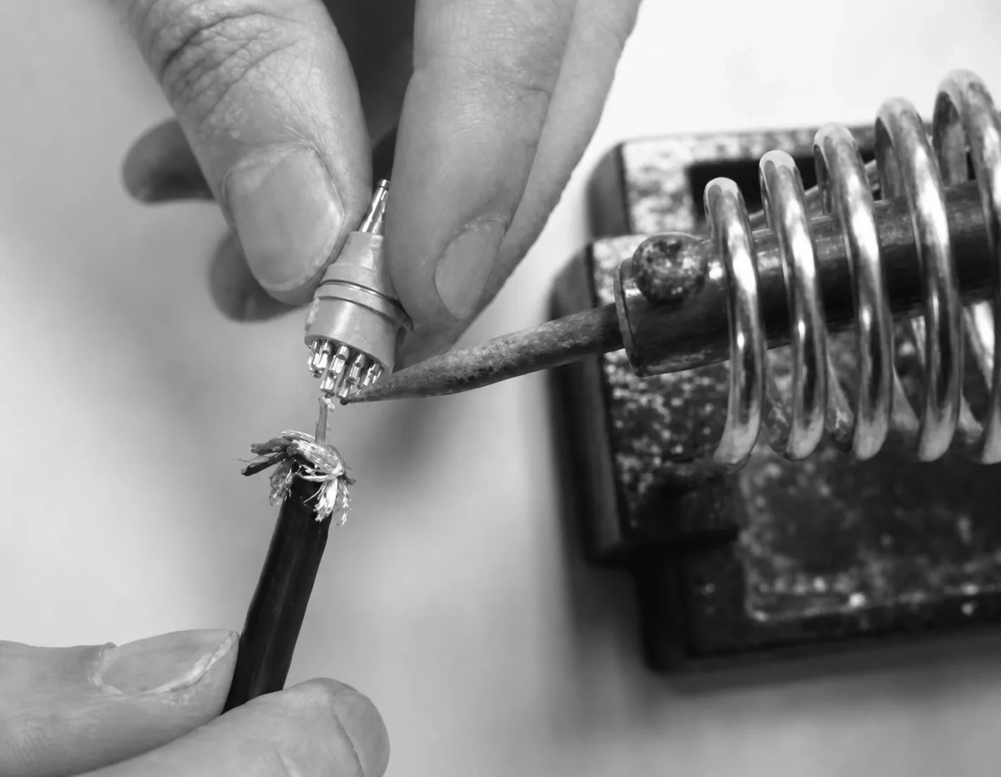
Soldering Guidelines
✦ The cable outer diameter must match the cable clamp size.
✦ The conductor size must be compatible with the contact termination diameter.
✦ For lead-free soldering, set the soldering iron temperature to approximately 380°C.
✦ Keep the soldering time for each conductor under 1 second.
✦ After soldering, insulate each conductor with heat-shrink tubing.
✦ Protect the contacts and insulator from damage during soldering.