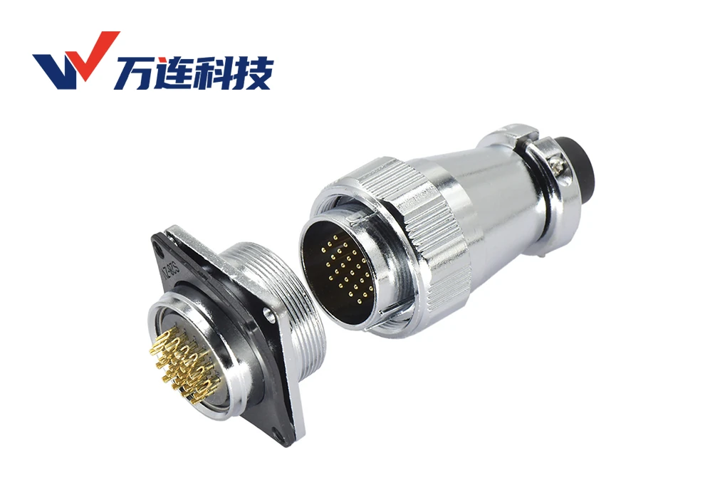
WLconnectivity DS16, DS20, DS24, and DS28 circular connector families can be evaluated for selected interfaces in small robot arms and servo modules where a multi-contact, metal-shell, threaded connection fits the packaging and service concept. The family name does not establish joint-level performance. Current, voltage, pin count, cable motion, shielding, ingress, vibration, and operating temperature must be confirmed for the exact plug, receptacle, insert, contact, and cable assembly.
A robot joint is a demanding location because space is limited while cables bend, twist, accelerate, and pass near motors and drives. In many designs, the better choice is to place the disconnect at a relatively stationary module boundary and allow a continuous motion-rated harness to pass through the moving section. A mechanically rugged connector installed directly at the highest-flex point can still fail through cable fatigue.
Define the joint boundary before choosing shell size
Decide what must be disconnected during assembly or service. A connector between arm modules may simplify production, motor replacement, or cable routing. An internal connection that is never serviced may add mass, length, and failure points without enough benefit. Map the installation sequence and determine whether technicians can see, align, and operate the connector.
Build a packaging model using the complete mated pair, coupling hardware, backshell, solder or wire exit, strain relief, cable bend radius, fastener access, and removal path. The nominal shell diameter is only part of the envelope. Check collision through the joint’s full range of motion and through manufacturing tolerances.
Separate power, brake, feedback, and communication
Robot joints may contain motor phases or DC power, brake circuits, encoders, temperature sensors, safety-related signals, and communications. A multi-pin connector can consolidate circuits, but mixing them requires an electrical and EMC review. Record voltage, continuous and peak current, duty cycle, signal type, impedance, reference, shielding, insulation, and fault consequence for every contact.
Do not assign a protocol from connector shape or contact count. A DS connector carrying differential signals is not automatically Ethernet, encoder-certified, or compatible with a servo vendor. High-speed channels require controlled pair geometry and measured performance through the contacts, cable, termination, and PCB. When the family lacks that evidence, keep the qualified standard data interface or develop a controlled proprietary link.
Apply product ratings by exact configuration
DS family ratings can change with shell size, contact count, contact geometry, wire size, and ambient temperature. Low-pin-count power inserts should not donate their current limit to dense signal inserts. Verify continuous and peak loads and measure temperature rise in the enclosed joint at maximum torque and duty cycle.
Voltage selection requires insulation coordination, including creepage, clearance, contamination, altitude, transients, and the applicable robot or machinery standards. A dielectric withstand value is a short test condition, not complete equipment approval. Provide overcurrent protection and protective bonding in the system architecture.
Threaded locking helps only when the installation is controlled
A threaded coupling provides positive engagement when correctly aligned and tightened. It can also be cross-threaded, left partially engaged, worn by unnecessary mating, or loosened if cable load and vibration act on the body. Use the supplier’s engagement instruction and design an anti-rotation and mounting strategy for the receptacle.
Support the harness so cable mass and dynamic force do not reach contacts or panel hardware. Test the production panel or module stiffness, not an ideal laboratory plate. Monitor all critical circuits for intermittent opens during vibration and shock, then inspect threads, contact wear, solder joints, shell bond, and receptacle retention.
The cable determines dynamic life
Define whether each joint section bends, rolls, twists, or combines motions. Specify bend radius, torsion angle, travel, speed, acceleration, cycle target, temperature, and routing. Select conductor stranding, pair design, shield, fillers, jacket, and strain relief for that exact motion.
Keep stiff connector transitions away from the highest curvature. Use guided service loops and clamps that preserve the cable’s neutral path without creating a sharp hinge. A metal shell cannot protect conductors from repeated strain created by poor routing.
Shielding and metal-shell bonding
The zinc-alloy metal shell described for DS products can provide mechanical protection and may participate in shielding. Effective EMC requires a controlled path from cable shield through backshell and mating shells to the intended joint chassis. Soldering a drain wire to any available point is not equivalent to a circumferential high-frequency bond.
Coordinate shield termination with motor-drive and robot grounding. Paint, lubricants, corrosion, or loose threads can change shell impedance. Test feedback and communications with motors switching and radios active, before and after motion and vibration aging.
Environmental limits and service
The source configuration describes industrial materials and a basic ingress level, but the exact rating must be checked for each part and installed state. Do not infer washdown, underwater, food-grade, cleanroom, or outdoor approval. Robot joints may encounter grease, oil, cleaning agents, dust, and temperature rise that require separate compatibility tests.
Gold-finished contacts can support corrosion and contact stability, while PPS can offer useful dimensional and heat resistance. Neither material guarantees the life of the assembly. Shell finish, contact underplate, seal, solder, cable jacket, and mating cycles all contribute.
Qualification plan for a joint interface
- Confirm exact DS plug, receptacle, contact layout, wire, cable, pinout, and mating drawing.
- Build the joint with production mounting, routing, supports, strain relief, and full motion envelope.
- Measure continuity, contact resistance, insulation, temperature rise, shielding, and data behavior as applicable.
- Operate the joint under maximum speed, acceleration, load, and nearby electrical noise.
- Apply mating cycles, vibration, shock, flex or torsion, thermal cycling, humidity, and fluids.
- Repeat electrical and functional tests and inspect contacts, solder joints, shell, threads, and cable exit.
- Run a service trial and freeze assembly, inspection, test, and spare-part instructions.
The WLconnectivity circular connector range provides DS-family and alternative starting points. For the routed cable system across several joints, robotics cable assembly options can be evaluated with the motion profile.
A DS connector is a candidate component, not a robot-joint guarantee. It becomes a reliable interface only when exact electrical limits, mounting, cable motion, shielding, environment, and service behavior are validated together.