An industrial robot depends on interconnects for motor power, brakes, encoders, safety circuits, control networks, cameras, sensors, end-of-arm tooling, pneumatics, and auxiliary equipment. These interfaces operate inside joints, along moving arms, through external dress packs, at the tool flange, and between the robot base and control cabinet. A connector that is reliable in a static machine can fail quickly when repeated bending, torsion, acceleration, side load, oil, or weld spatter is added.
Robot connectivity should therefore be designed from the motion profile outward. The cable, conductor, shield, connector, overmold, backshell, strain relief, clamp, carrier, routing, and service loop form one dynamic system. Miniaturization and high data rates are useful only when that system maintains power, signal integrity, safety performance, and mechanical life in the real robot application.
Map every circuit and motion zone, then specify voltage, current-time profile, data protocol, shielding, safety function, bend radius, torsion, travel, speed, acceleration, cycle profile, cable length, routing, temperature, chemicals, ingress, weld exposure, and maintenance access. Distinguish static, occasional-flex, continuous-flex, torsional, and combined-motion cable segments. Select connectors with suitable contact systems, locking, coding, shell grounding, retention, and environmental protection for the exact cable and installation. Validate the complete dress pack or internal harness on representative robot motion while monitoring temperature, continuity, communication errors, shield integrity, and mechanical wear. Connector ratings alone do not predict dynamic system life.
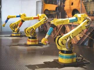
Build a Connectivity Map by Robot Zone
| Zone | Typical interfaces | Primary design concerns |
|---|---|---|
| Control cabinet to base | Supply, drive, protective bonding, safety, field network | Current, EMC, coding, field installation, service disconnect |
| Internal axes | Motor, brake, encoder, temperature, internal network | Tight space, repeated bend and torsion, thermal load, inaccessible repair |
| External dress pack | Tool power, signals, data, air, fluids | Routing, clamps, collision, abrasion, hose interaction, service life |
| Wrist and tool flange | Gripper, welder, vision, force sensor, tool changer | High acceleration, compactness, frequent tool change, contamination |
| Cell peripherals | Safety devices, fixtures, conveyors, sensors, cameras | Network architecture, field wiring, ingress, diagnostics, replacement |
The map should identify which interfaces move, which remain static, which can be disconnected by operators, and which are service-only. It should also show separation or coordination between power, data, safety, pneumatic, and fluid paths. Do not route a delicate high-speed cable as if it were a rugged air hose, or let a heavy hose impose torsion on a connector backshell.
Motion Profile Is the Starting Specification
“Robot cable” is not a complete requirement. Record minimum bend radius, bend direction, travel, torsion angle per length, speed, acceleration, dwell, cycle frequency, operating hours, temperature, bundle construction, and expected service interval. A cable rated for repeated flex in a linear carrier may not tolerate continuous torsion around a robot axis. A torsion-rated cable may still fail if clamped at the wrong distance or bent below its dynamic radius.
Use the robot program or digital model to identify worst axes and simultaneous movements. Observe whether the bundle snaps, rubs, buckles, twists at a connector, reaches its limit, or collides with the cell. Payload, tool orientation, program changes, and operator jogging can produce a different path from the qualification cycle. Include reasonably foreseeable setup and recovery motions.
Control Cable Construction and Routing
Continuous-motion cables use conductor stranding, insulation, shield, fillers, tapes, jacket, and lay geometry selected for repeated movement. These choices affect flex life, diameter, impedance, attenuation, torsion, chemical resistance, and cost. Cable-family claims should be tied to the actual part number, motion type, bend radius, bundle, and test method.
Route the dress pack near the intended neutral path and provide controlled service loops. Use clamps or carriers that support the bundle without crushing it. Separate components that rub or migrate. Prevent weight and repeated motion from reaching connector contacts or solder joints. Backshells and overmolds should transition stiffness gradually; a very rigid termination can move the fatigue point into the cable.
Installation workmanship matters. Cable twist introduced during assembly, incorrect clamp orientation, over-tightened ties, missing separators, and short service loops can consume life before production begins. Mark alignment and clamp locations, verify the neutral position, and release a visual routing standard for each robot program or tool configuration.
Match Connector Design to Electrical Function
Motor power and brakes require current capacity, low and stable resistance, insulation, protective bonding, and EMC control. Encoder and sensor circuits may need low-noise contacts and shield continuity. Industrial Ethernet, camera, or high-speed links require controlled channel performance through cable, connectors, and PCB transitions. Safety circuits require an architecture that achieves the required risk reduction; a connector does not become a safety device merely because it carries safety signals.
Define contact sequencing where it matters, coding to prevent wrong mating, locking for vibration and motion, service access, tool requirements, and mating-cycle expectations. Compact hybrid connectors can combine power, data, and signals, but they also introduce thermal coupling, insulation, crosstalk, repair, and keying questions. A modular multi-connector approach can improve service but requires more space and interfaces. Compare total system risk and maintenance time, not connector count alone.
Data Performance Is Not Created by 5G or a Small Connector
Wireless technologies, including private 5G networks, may support factory-level communication, monitoring, or mobile equipment. They do not remove the robot’s need for wired motor power, feedback, safety, tool signals, and many deterministic internal links. Nor does 5G determine the bandwidth of a connector. The end-to-end protocol, cable, channel length, shielding, controller, switch, traffic design, and application latency determine performance.
For wired high-speed links, review insertion loss, return loss, crosstalk, common-mode conversion, shield termination, connector transitions, and bend-induced changes. Monitor packet or frame errors during representative motion, including simultaneous motor switching and welding or drive noise. A static network test may miss an intermittent shield or conductor fault that appears only at one robot pose.
EMC and Shield Termination Need Mechanical Durability
A cable shield is useful only when its termination remains electrically and mechanically stable. Pigtails can add inductance at high frequency; incomplete circumferential contact can reduce shielding. Yet a rigid 360-degree clamp without proper strain transition may accelerate fatigue. The connector, backshell, gland, braid termination, enclosure bond, and grounding architecture should be designed together.
Test shield resistance and transfer behavior before and after dynamic aging where EMC risk warrants it. Inspect braid breakage, foil cracking, connector-shell wear, corrosion, and grounding hardware. Route noisy drive conductors and sensitive feedback according to the system EMC plan and preserve separation at moving transitions.
Environment and Application Hazards
Welding cells can expose cables and connectors to hot spatter, electromagnetic noise, smoke, and abrasive debris. Machining adds oil, coolant, chips, and washdown. Food, pharmaceutical, cleanroom, freezer, foundry, or outdoor applications have different material and cleaning requirements. Select jackets, seals, housings, metals, and protective sleeves for the actual fluids, temperature, radiation, and mechanical exposure.
An IP code applies to a defined enclosure condition and test. It may not cover unmated connectors, damaged caps, dynamic cable side load, pressure washing chemicals, or an aged overmold. Define mated, unmated, cleaning, tool-change, and maintenance states. Verify electrical performance after the relevant combined environmental and motion sequence.
Robot Safety Standards and Connector Scope
ISO 10218-1:2025 addresses safety requirements for industrial robots, while ISO 10218-2:2025 addresses industrial robot applications and robot cells. The distinction matters: a robot supplied as partly completed machinery is not the same as a fully integrated cell with tooling, guarding, peripherals, and application hazards. IEC 60204-1 applies to electrical equipment of machinery within its scope and addresses topics including protective bonding, control circuits, and documentation.
These standards guide the system safety process; they do not provide a blanket approval for any connector or cable. The integrator must perform risk assessment, define safety functions, achieve required performance, prevent common-cause failures, and validate the complete cell under applicable market rules. Application hazards such as welding, laser processing, machining, or handling dangerous materials require additional measures.
Qualification Should Reproduce the Dynamic System
- Freeze the configuration. Document robot model, program, tool, cable, connector, routing, clamps, carrier, bundle, and environment.
- Measure initial performance. Record continuity, resistance, insulation, temperature, signal integrity, shield behavior, force, and visual condition.
- Run representative motion. Reproduce bend, torsion, speed, acceleration, dwell, concurrent axes, current loading, and environmental exposure.
- Monitor during the test. Detect micro-interruptions, communication errors, temperature, leakage, and position-dependent failures.
- Inspect at intervals. Look for conductor fatigue, jacket cracking, abrasion, braid damage, seal movement, loose locks, and clamp migration.
- Repeat critical measurements. Establish drift and failure criteria, then correlate bench results with pilot and field data.
Production and Predictive Maintenance
Control stripping, crimping or soldering, shield termination, overmolding, connector assembly, sealing, routing marks, and electrical tests. Trace the finished harness to component lots, tooling, programs, and test results. Changes to cable materials, lay length, conductor stranding, jacket, plating, mold process, clamp, or robot motion require an impact review.
In service, track cycles or operating hours by robot and tool configuration, not calendar age alone. Useful indicators include communication error rate, intermittent faults by pose, temperature trend, resistance drift, jacket wear, clamp movement, and unplanned stops. Replace at a condition- or risk-based interval before failure, but do not assume one interval fits every axis or program.
Procurement Questions for Robot Interconnects
- Is the cable qualified for continuous bending, torsion, or the actual combined motion?
- Which bend radius, torsion, travel, speed, acceleration, bundle, and temperature support the life claim?
- How are connector side load, strain relief, shielding, locking, and sealing validated after motion?
- What electrical and data tests run during dynamic cycling rather than only afterward?
- Which materials withstand the specified oils, coolants, cleaning agents, spatter, and abrasion?
- What production changes require notification and repeat qualification?
Frequently Asked Questions
Can a standard industrial cable be used on a robot arm?
Only if its documented motion, electrical, and environmental capability matches the installation. Static, drag-chain, torsion, and combined-motion cables are not automatically interchangeable.
Does a smaller connector improve robot performance?
It can reduce mass and space, but only if thermal, insulation, signal, locking, service, and mechanical margins remain adequate.
Can an IP-rated connector be pressure-washed indefinitely?
No. Verify the tested state, pressure, direction, duration, water conditions, chemicals, aging, and cable installation. Damage or unmated exposure can change protection.
What is the best predictor of robot cable life?
A representative dynamic test and field trend for the exact cable, bundle, routing, motion, environment, and electrical load are more useful than a generic cycle number.
Engineer the Full Robot Dress Pack
Teams selecting dynamic assemblies can review WLconnectivity cable assemblies for robotics. For the wider interface architecture, see its robotics connectivity and interconnect solutions. Reliable automation comes from matching every connection to its motion zone, electrical function, environment, production process, and service plan.