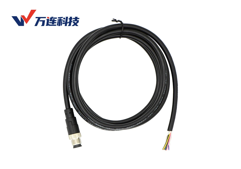
A molded M12 connector does not by itself make a cable assembly suitable for continuous motion. Drag chains mainly impose repeated bending, while robot joints can add torsion, bending in multiple planes, acceleration, abrasion, and changing tensile load. The entire harness—conductors, insulation, pair geometry, shield, fillers, jacket, overmold transition, connector mounting, and routing—must be designed and qualified for the actual motion.
The selection process should convert the robot trajectory into measurable cable requirements: minimum dynamic bend radius, bend direction, torsion angle per meter, travel length, speed, acceleration, cycles, temperature, chemical exposure, and allowable signal degradation. Product claims such as “high-flex” or “robot cable” are not interchangeable without their test conditions.
Distinguish repeated bending from torsion
| Motion | Dominant stress | Typical design response |
|---|---|---|
| Drag-chain travel | Repeated bending in a controlled plane, acceleration, and cable-to-cable interaction | Chain-rated cable, defined dynamic radius, neutral placement, controlled fill and guidance |
| Robot-axis torsion | Repeated angular displacement along cable length | Torsion-rated construction, adequate free length, controlled attachment and angle per meter |
| Dress-pack compound motion | Bending, torsion, whipping, and local tensile load | Trajectory simulation, guides, strain relief, service loop, and physical endurance testing |
| Occasional service movement | Low cycle count with possible tight manual bends | Minimum radius, handling instructions, connector protection and inspection |
A cable optimized for millions of planar flex cycles may fail rapidly when twisted. Conversely, a torsion-rated cable can be damaged in a poorly filled drag chain. State the motion profile in the RFQ and ask the supplier for an applicable test method, not just a cycle number.
Cable construction controls fatigue life
Fine-stranded conductors can distribute bending strain, but strand count alone is insufficient. Lay length, bunching, conductor material, insulation, core arrangement, fillers, tapes, shield, and jacket determine how the cable moves internally. Balanced construction helps prevent conductors from migrating or concentrating stress. The conductor size must still satisfy resistance, voltage drop, current, and temperature requirements.
Shielded dynamic cable needs special attention. A conventional dense braid may experience fatigue or change geometry during repeated motion. Spiral shields, optimized braids, foils, and hybrid constructions each involve tradeoffs in flex life, coverage, resistance, and high-frequency performance. For Ethernet or encoder links, verify that impedance, pair balance, attenuation, and shield continuity remain within limits after motion conditioning.
The overmold transition is a critical stress zone
Overmolding seals and supports the cable-to-connector transition, but an abrupt stiffness change can create a fatigue hotspot. The strain-relief geometry, material hardness, bond to the cable jacket, cable exit direction, and nearby clamp location should produce a gradual transition. The harness should not begin its dynamic bend immediately at the rear of the connector.
A right-angle body may improve packaging, but its clocking relative to the M12 key must match the equipment route. If installation forces the cable to twist just to reach the chain, the nominally correct connector has created a permanent preload. Freeze the orientation on a drawing with a defined viewing convention.
Route the harness as a mechanical subsystem
- Model the full robot envelope and find the maximum bend, torsion, extension, and interference positions.
- Keep the cable within the manufacturer’s dynamic bend radius throughout the trajectory.
- Provide enough free length for motion without creating loops that strike surrounding structures.
- Locate clamps on suitable stationary regions and avoid crushing the jacket or overconstraining torsion.
- In a drag chain, follow fill, separation, weight distribution, and end-fixing instructions.
- Prevent rubbing against sharp edges, weld spatter, hot surfaces, and moving mechanical components.
- Make the dress pack inspectable and replaceable without disturbing unrelated axes.
Routing trials should use the real connector, cable length, tooling, and payload. A digital model may miss friction, bundle growth, temperature stiffness, and operator installation variation.
Electrical requirements remain part of dynamic design
Select M12 coding and contact count from the equipment interface. Check current per loaded contact under the maximum ambient and bundle condition. For DC power, calculate round-trip voltage drop and inrush. For data, use a protocol-appropriate cable and qualify the entire moving channel. For low-level sensors, review shielding and ground reference. A mixed harness may need physical separation between noisy power and sensitive signals.
Repeated motion can create intermittent opens before a conductor fails completely. Monitoring only static continuity at rest may miss the defect. During endurance testing, move the cable while measuring conductor resistance or continuity with sufficient sampling, and monitor data errors for communication circuits.
Build a defensible endurance test
Use the production cable, overmold, connector, clamp, bend radius, torsion length, speed, acceleration, temperature, and routing. Test at the worst credible combination, while recognizing that an overly artificial combination may create a failure mode that never occurs in service. Define the cycle, direction changes, dwell, and inspection interval so results are reproducible.
Acceptance criteria may include no opens or shorts, bounded resistance change, stable shield continuity, acceptable channel performance, no jacket cracking, no overmold separation, no contact movement, and maintained sealing after conditioning. Section failed samples to identify whether the root cause is conductor fatigue, shield damage, jacket wear, termination strain, or routing.
Plan inspection and replacement before production
Record a baseline for communication errors, resistance, or image quality at commissioning. Inspect high-motion zones for polishing, flattening, jacket cracks, exposed braid, displaced clamps, and changing loop geometry. Use cycle or condition data to schedule replacement where an unexpected failure would stop a line or create a hazard. A modular harness that can be replaced quickly may provide more lifecycle value than a theoretically longer-lived but inaccessible assembly.
For application planning, review robotics cable assembly options alongside the broader robotic-arm connectivity architecture. Final qualification should reproduce the intended axis motion and environment.
Frequently Asked Questions
Is a PUR jacket enough to make a cable drag-chain rated?
No. Jacket material is only one factor. Conductor, insulation, core, shield, lay, and the tested motion profile determine dynamic suitability.
Can a drag-chain cable be used for robot torsion?
Only if the manufacturer specifies and validates the required torsion. Planar flex and torsion produce different internal stresses.
Where should the first clamp be placed?
Use the cable and connector manufacturer’s guidance and the routing design. It should support the connector without forcing the dynamic bend into the overmold transition.
What should be monitored during a flex test?
At minimum, opens, shorts, resistance change, shield continuity, physical damage, and connector retention. Add live protocol or signal measurements for the actual interface.